Table of Contents

What is a Piping Drawing and Its Key Engineering Types?
In my 20-plus years of managing piping engineering projects, I have seen millions of dollars lost on site simply because of a single misinterpretation of a piping drawing. When you are standing in the middle of a multi-billion dollar petrochemical facility, the piping drawing is your map, your contract, and your safety shield. It is not merely a collection of lines and symbols; it is a precise mathematical representation of fluid dynamics, structural mechanics, and spatial coordination.
I often tell my junior engineers that a drawing must speak for itself. If a fabricator in the yard has to call you to ask what a weld symbol means or where a support goes, your drawing has failed. To prevent these field errors, we rely on a structured hierarchy of drawings, ranging from conceptual process diagrams to highly detailed three-dimensional isometric layouts.
Key Takeaways from This Guide
- Understand the fundamental differences between P&IDs, Isometrics, and General Arrangement (GA) drawings.
- Learn how to apply ASME B31.3 design rules directly to drawing interpretations.
- Discover the exact calculations used to verify pipe wall thickness and thermal expansion on drawings.
- Access a field-tested checklist to verify drawings before releasing them to the fabrication yard.
- Explore a real-world case study where a drawing error cost a project weeks of delay, and how we resolved it.
How Does a Piping Drawing Guide Industrial Construction?
To truly master the interpretation of a piping drawing, we must break down the system into its core components. Every line on that sheet represents a physical pipe that must withstand high pressures, extreme temperatures, and corrosive fluids. The design of these lines is governed by strict international standards, primarily the ASME B31.3 Process Piping Code.
The Mathematical Foundation of Piping Design
When I review a piping drawing, the first thing I verify is the pipe wall thickness. This is not a random selection; it is calculated using the ASME B31.3 Section 304.1.2 formula for straight pipe under internal pressure:
Where:
- t = Pressure design thickness (inches or millimeters)
- P = Internal design gage pressure (psi or MPa)
- D = Outside diameter of the pipe (inches or millimeters)
- S = Allowable stress value for the material at design temperature (psi or MPa)
- E = Quality factor from ASME B31.3 Table A-1A or A-1B
- W = Weld joint strength reduction factor per ASME B31.3 Section 302.3.5(e)
- Y = Coefficient from Table 304.1.1, which depends on material and temperature
Once the design thickness “t” is calculated, we must add allowances for corrosion, erosion, and mechanical strength (such as thread depth), plus a 12.5% manufacturing tolerance to select the final nominal pipe schedule shown on the piping drawing.
Never ignore the thermal expansion loops indicated on a piping drawing. If a field crew shortens a run or eliminates a loop to save space, the resulting thermal stress can easily exceed the allowable limits of ASME B31.3, leading to catastrophic flange leaks or nozzle failures at connected equipment.
Understanding the Three Main Types of Piping Drawings
In industrial projects, we use three primary drawing types to execute a design from concept to construction:
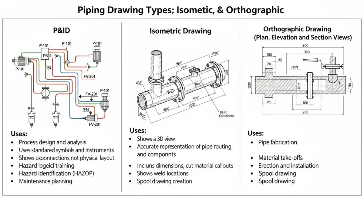
- Process and Instrumentation Diagrams (P&ID): These are schematic drawings that show the functional relationship between piping, instrumentation, and system equipment. They are not drawn to scale and do not show physical routing, but they are the absolute authority on process flow, valve sequences, and safety interlocks.
- Isometric Drawings: These are three-dimensional, single-line representations of a single pipe line. They are drawn at a 30-degree angle, allowing the fabricator to see the length, width, and depth of the run on a single sheet. They include a complete Bill of Materials (BOM) with exact cut lengths.
- General Arrangement (GA) Drawings: These are orthographic (plan and elevation) views of the entire piping system within a specific area. They are drawn to scale and are used by civil and structural teams to coordinate pipe rack space, structural steel supports, and equipment foundations.
To ensure consistency across global engineering teams, piping drawings utilize standardized symbols and representations. Below is a comprehensive comparison of how different drawing types represent key system parameters.
| Drawing Type | Scale Requirement | Primary Purpose | Key Standards | Bill of Materials (BOM) |
|---|---|---|---|---|
| P&ID | Not to Scale | Process flow, control logic, and safety systems | ISA 5.1, PIP PIC001 | No |
| Isometric | Not to Scale (Proportional) | Shop fabrication and field erection of individual lines | ASME Y14.3, ASME B31.3 | Yes (Detailed with cut lengths) |
| Orthographic (GA) | Strictly to Scale (e.g., 1:33) | Spatial coordination, civil foundations, and structural support | ASME Y14.3, PIP PNE0001 | Sometimes (Bulk materials only) |
This matrix maps the core technical entities, structural acronyms, and physical parameters that you will encounter on any standard industrial piping drawing.
| Entity / Acronym | Full Technical Name | Physical Parameter Represented | Governing Code / Reference |
|---|---|---|---|
| BOP | Bottom of Pipe | Elevation of the lowest outer surface of the pipe run | ASME Y14.38 |
| FOB | Flat on Bottom | Eccentric reducer orientation to prevent liquid pooling | ASME B16.9 |
| TOS | Top of Steel | Elevation of the supporting structural steel beam | AISC Steel Construction Manual |
| NPS | Nominal Pipe Size | Standardized dimensionless designator for pipe diameter | ASME B36.10M |
Why Verify a Piping Drawing Before Field Fabrication?
Before any pipe is cut or welded in the fabrication shop, a rigorous verification process must occur. In my experience, skipping this step is the leading cause of piping clashes and alignment issues during field installation. Use the checklist below to verify your drawings against actual site conditions.
Field Verification Checkpoints
-
Tie-In Point Verification: Physically measure and verify the coordinates and elevations of existing equipment nozzles or piping tie-ins. Do not rely solely on old “as-built” drawings.
-
Clearance and Clash Check: Ensure there is a minimum of 2 inches (50 mm) of clearance between the insulated pipe surface and adjacent structural steel, electrical trays, or civil foundations.
-
Valve Accessibility: Verify that handwheels, chain operators, and instrument displays are positioned within reach of operators (typically between 3 feet and 6 feet above the high point of the platform).
-
Slope and Drainage: For lines requiring gravity flow or self-draining (such as steam condensate or flare headers), verify that the slope direction and angle are clearly marked and physically achievable.
-
Support Locations: Confirm that structural steel is available at the exact locations specified for pipe shoes, guides, and anchors.
-
Weld Gap and Fit-Up: Ensure the drawing accounts for standard weld gaps (typically 1/16 inch to 1/8 inch) in the overall dimension calculations.
Field Case Study: Real-World Application
The Problem: The Costly Steam Line Clash
During a major refinery expansion project, a 12-inch high-pressure steam line (operating at 600 psi and 750 degrees Fahrenheit) was fabricated off-site based on an approved isometric drawing. When the field crew attempted to install the line, they discovered a massive clash: the pipe run went directly through a newly installed structural steel diagonal brace. The isometric drawing had been created using an outdated structural model that did not include the brace.
The Outcome: 3D Laser Scanning and Rapid Redesign
To resolve the issue without delaying the entire project, we immediately deployed a 3D laser scanner to capture the exact “as-built” spatial coordinates of the structural steel and surrounding piping. We imported the point cloud data directly into our 3D modeling software. Within 24 hours, we rerouted the steam line, added a new thermal expansion loop to compensate for the change in routing, and generated a revised isometric drawing. The pipe was modified in the field yard, hydrotested, and installed with zero further clashes.
This incident reinforced a fundamental rule in my engineering practice: always coordinate your piping drawings with the latest structural and civil models. A piping drawing does not exist in a vacuum; it must be integrated with every other engineering discipline on the project site.
Frequently Asked Engineering Questions
What is the difference between a PFD and a P&ID?
Why are isometric drawings not drawn to scale?
What does “BOP” mean on a piping drawing?
How do you show a slope on a piping isometric drawing?
Which ASME code governs piping drawing symbols?
What is a spool drawing in piping?
===
Complete Course on
Piping Engineering
Check Now
Key Features
- 125+ Hours Content
- 500+ Recorded Lectures
- 20+ Years Exp.
- Lifetime Access
Coverage
- Codes & Standards
- Layouts & Design
- Material Eng.
- Stress Analysis

📚 Recommended Resources: piping drawing
Read these Guides
🎓 Advanced Training


Related posts:
![Professional land surveyor using a total station for a topographic survey in an open field]()
Understanding Land Mapping and the True Topographic Survey Cost
![Side-by-side comparison of an industrial centrifugal pump and a rotary screw compressor.]()
What is the Difference Between Pump and Compressor Systems?
![Cutaway 3D render of an industrial air-operated double-diaphragm pump showing internal components.]()
Understanding Diaphragm Pumps: A Comprehensive Guide for Industrial Plants
![A metallic pipe sleeve embedded in a concrete wall with a carrier pipe passing through it.]()
What is a Pipe Sleeve and How Does It Protect Piping?
![Industrial stainless steel swing check valve installed in a pipeline with a flow direction arrow.]()
What are Check Valves? Types of Check Valves & Their Symbols
![Cross-section diagram of a control valve showing cavitation bubbles and flashing liquid.]()
How to Prevent Control Valve Cavitation and Flashing Damage