What is a Concrete Pump and How Does It Work?
In my 20 years of managing heavy civil and high-rise structural pours, I have seen many projects succeed or fail based on a single factor: how efficiently we move wet concrete from the transit mixer to the formwork. Before the widespread adoption of the modern concrete pump, we relied on cranes, buckets, and wheelbarrows. That manual approach was slow, labor-intensive, and prone to segregation of the concrete mix.
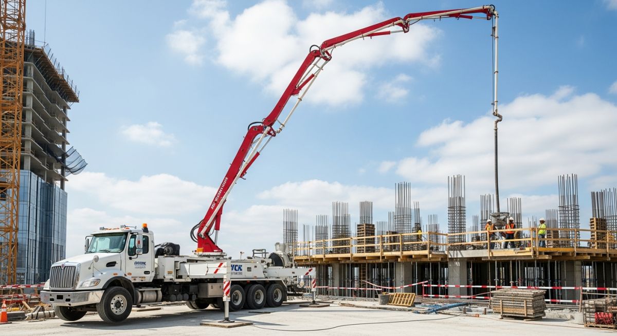
Today, a high-performance concrete pump is the beating heart of any major structural pour. Whether we are casting a massive foundation raft or pumping high-strength mix up 60 stories, understanding the mechanics, hydraulics, and operational limits of these machines is a fundamental requirement for any site engineer. In this guide, I will share my hands-on field experience regarding how these systems operate, how to select the right type for your project, and how to avoid the costly pipeline blockages that can ruin a pour.
Key Engineering Takeaways
- Learn the mechanical differences between high-volume boom pumps and high-pressure line pumps.
- Understand the hydraulic physics governing concrete flow and pipeline pressure drops.
- Master the critical concrete mix design parameters required to prevent line blockages.
- Implement field-tested safety protocols in compliance with ASME B30.27.
Complete Course on
Piping Engineering
Check Now
Key Features
- 125+ Hours Content
- 500+ Recorded Lectures
- 20+ Years Exp.
- Lifetime Access
Coverage
- Codes & Standards
- Layouts & Design
- Material Eng.
- Stress Analysis
How Does a Concrete Pump Operate Under Pressure?
To truly understand a concrete pump, we must look at the dual-cylinder reciprocating hydraulic system. This is the industry standard for high-pressure concrete delivery. The system consists of two parallel concrete cylinders equipped with heavy-duty polyurethane pistons. These pistons are connected via drive rods to two hydraulic cylinders driven by a high-displacement hydraulic pump.
The operation is a continuous, alternating cycle:
- The Suction Stroke: As hydraulic cylinder A retracts, it pulls concrete piston A backward. This action creates a vacuum inside concrete cylinder A, drawing fresh concrete from the hopper into the cylinder.
- The Discharge Stroke: Simultaneously, hydraulic cylinder B extends, pushing concrete piston B forward. This forces the concrete out of cylinder B and into the delivery pipeline.
- The Valve Shift: At the end of each stroke, a high-speed valve (typically an S-valve or S-tube) shifts its position. It aligns with the discharging cylinder while opening the other cylinder to the hopper. This shift must occur in milliseconds to maintain a steady, pulse-free flow.
The Physics of Concrete Flow and Pressure Drop
Pumping concrete is not like pumping water. Concrete is a non-Newtonian, highly viscous suspension of aggregates in a cement paste matrix. To pump it successfully, we must overcome the friction between the concrete and the steel pipe wall. This requires establishing a “lubricating layer” of water and cement paste along the inner pipe surface.
In my practice, I use a simplified pipeline pressure drop calculation to verify if our pump has sufficient hydraulic capacity. The total pressure required at the pump outlet can be calculated using this engineering formula:
Where:
P_total = Total required pump pressure (Pa or bar)
P_friction = Friction pressure loss per meter of pipe (typically 1.0 to 2.5 bar/m depending on pipe diameter and mix design)
L = Total equivalent length of the pipeline, including horizontal runs and equivalent lengths for bends (m)
rho = Density of wet concrete (typically 2400 kg/m³)
g = Acceleration due to gravity (9.81 m/s²)
H = Vertical pumping height (m)
Every 90-degree bend in a 5-inch pipeline adds an equivalent horizontal length of approximately 3.0 meters. If your field crew adds unnecessary elbows to route around obstacles, they can easily push the required pressure beyond the pump’s maximum hydraulic limit, leading to immediate line blockages and hydraulic relief valve trips.
Concrete Mix Design for Pumpability
You can have the most powerful concrete pump on earth, but if your mix design is wrong, the line will block within minutes. The mix must be cohesive enough to resist segregation under high pressure, yet fluid enough to flow. Key parameters include:
- Aggregate Grading: The maximum aggregate size should not exceed one-third of the internal diameter of the delivery pipe. For a standard 5-inch (125 mm) pipe, the maximum aggregate size is 40 mm, though 20 mm is highly preferred for trouble-free pumping.
- Sand Content: A higher sand-to-aggregate ratio (typically 38% to 45%) is required compared to non-pumped mixes to fill the voids between larger stones and retain water.
- Slump and Workability: A slump of 100 mm to 150 mm is ideal for standard pumping. For high-rise applications, we use self-consolidating concrete (SCC) with a flow spread of 600 mm to 700 mm, achieved using high-range water reducers (superplasticizers).
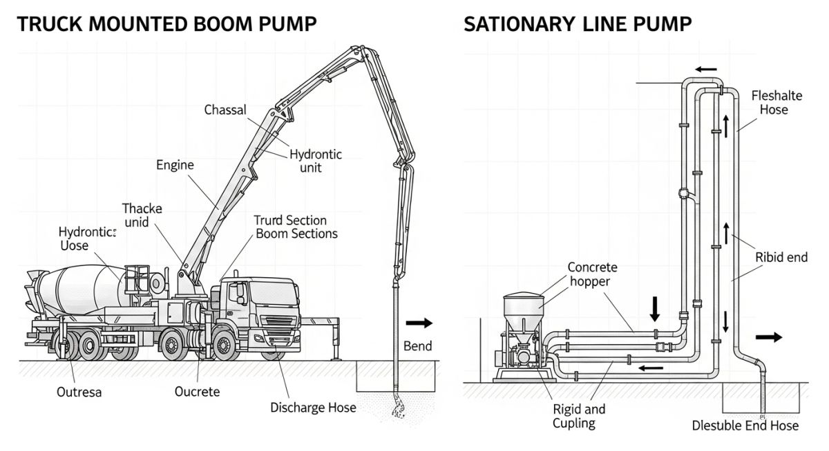
Selecting the correct concrete pump requires matching the project’s spatial constraints with the pump’s mechanical capabilities. The table below outlines the typical engineering specifications for the two primary classes of concrete pumps used in modern infrastructure projects.
| Specification Parameter | Truck-Mounted Boom Pump | Stationary Line Pump |
|---|---|---|
| Typical Volumetric Output | 60 to 185 m³/hour | 30 to 120 m³/hour |
| Maximum Concrete Pressure | 70 to 85 bar | 100 to 250+ bar |
| Maximum Vertical Reach | 16 to 65+ meters (Boom limit) | 300+ meters (Pipeline limit) |
| Maximum Horizontal Reach | 12 to 60+ meters | 1000+ meters |
| Primary Application Scope | Rapid placement, bridges, slabs | High-rise, tunnels, long-distance |
Technical Mapping & Specifications Matrix
To ensure full compliance with international design codes, engineers must map physical parameters to the correct regulatory standards. The matrix below serves as a quick reference for design and field verification.
| Entity / Acronym | Physical Parameter | Design Limit / Value | Standard Reference |
|---|---|---|---|
| ACPA | Operator Certification & Safety | Mandatory field testing | ACPA Safety Manual |
| ASME B30.27 | Pipeline Wall Thickness | Min 4.0 mm for 5-inch steel | ASME B30.27-2020 |
| ACI 304.2R | Concrete Mix Pumpability | Slump: 100 to 150 mm | ACI 304.2R Guide |
| EN 12001 | Safety Requirements for Pumps | Dual-channel safety switches | BS EN 12001 |
Essential Safety Checks for a Concrete Pump
Before the first transit mixer backs up to the hopper, the site engineer and pump operator must conduct a rigorous physical inspection. A failure during a high-pressure pour is not just a quality issue; it is a severe safety hazard. High-pressure concrete lines can whip violently if they rupture or if air becomes trapped in the system.
Field Verification Protocol
-
Outrigger Ground Support: Verify that all outriggers are fully extended and positioned on heavy-duty timber pads or steel plates. The ground bearing capacity must exceed the maximum outrigger load specified by the manufacturer.
-
Pipeline Coupling Inspection: Physically inspect every coupling. Ensure all safety pins are inserted and secure. Never use worn, single-bolt clamps on high-pressure lines; always use heavy-duty, two-bolt or wedge-lock couplings.
-
Wall Thickness Verification: Use an ultrasonic thickness gauge to check the high-wear areas of the pipeline, especially the first 90-degree elbow exiting the pump. Replace any pipe section that has worn below 90% of its original wall thickness.
-
Overhead Power Line Clearance: Maintain a minimum clearance of 6.0 meters (20 feet) from all overhead power lines. If working closer, verify that the utility company has de-energized or shielded the lines.
-
Priming Slurry Readiness: Ensure a minimum of 200 liters of cement-sand slurry or a proprietary chemical priming agent is ready in the hopper to lubricate the line before concrete pumping begins.
Field Case Study: Real-World Application
The Problem: High-Rise Pipeline Blockages
During the construction of a 55-story commercial tower, the field crew experienced repeated pipeline blockages at level 32 (approximately 128 meters vertical height). The stationary concrete pump was operating near its maximum hydraulic pressure of 220 bar, but the concrete mix was segregating inside the vertical riser. This caused immediate line blockages, resulting in cold joints in the core wall pours and hours of downtime spent dismantling and cleaning the high-pressure steel pipes.
The Engineering Solution
I was called to site to audit the operation. We identified three critical issues: the sand-to-aggregate ratio was too low (34%), the vertical riser was not anchored properly, causing severe pipe vibration that promoted mix segregation, and the S-valve was worn, allowing cement paste to leak back into the hopper.
We implemented immediate corrective actions:
- Redesigned the concrete mix, increasing the sand ratio to 41% and adding a silica-fume-based pumping aid.
- Installed heavy-duty structural brackets to anchor the vertical riser at every third floor, eliminating pipe vibration.
- Replaced the worn S-valve and seals on the stationary pump to restore full hydraulic efficiency.
The Outcome: Following these modifications, the concrete pressure stabilized at a manageable 145 bar. We completed the remaining 23 stories without a single pipeline blockage, saving an estimated 120,000 in labor and material waste, while ensuring the structural integrity of the tower’s core walls.
Frequently Asked Engineering Questions
What is the maximum height a concrete pump can reach?
How do you prevent blockages in a concrete pump pipeline?
What is the difference between an S-valve and a rock valve?
Why is priming the concrete pump pipeline necessary?
What are the key safety clearances for boom pumps near power lines?
How does aggregate size affect concrete pump performance?
===

📚 Recommended Resources: concrete pump
Read these Guides


Related posts:
![Professional surveyor conducting Topographical Surveys for Solar Projects on a large-scale utility site with complex terrain.]()
Topographical Surveys for Solar Projects: A Technical Engineering Guide
![A geotechnical drill rig performing soil sampling on a large, open field intended for a utility-scale solar farm project.]()
Geotechnical Investigation for Solar Farms: Essential Site Design Guide
![Isometric site plan showing Utility Corridor Planning for Data Centres with color-coded power, water, and telecom infrastructure paths.]()
Utility Corridor Planning for Data Centres: A Strategic Engineering Guide
![Aerial view of a data centre site showcasing perimeter drainage systems, detention basins, and site grading for flood prevention.]()
Drainage Design Considerations for Data Centres: A Technical Guide
![Professional surveyor using a Total Station on a large data centre construction site for topographical mapping.]()
Topographical Surveys for Data Centre Projects: A Technical Guide
![Cross-section diagram showing Ground Improvement for Data Centres using stone columns and deep soil mixing beneath a concrete foundation slab.]()
Ground Improvement for Data Centres: Engineering Stability and Settlement Control