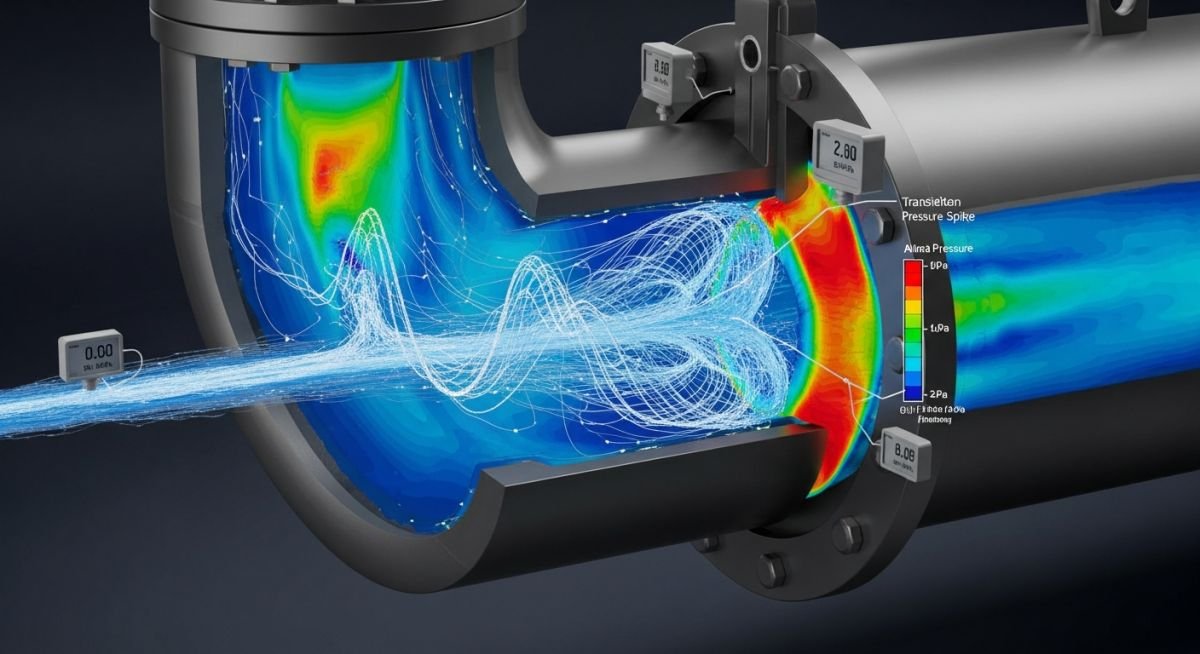
Water Hammer Basics in Pumps: Preventing Catastrophic Pipe Failure
In my two decades of field experience, I have seen too many pump stations crippled by the violent, rhythmic thumping of water hammer. It is not just noise; it is a high-energy shockwave traveling through your piping at the speed of sound, often exceeding the design pressure of your valves and fittings. When a pump trips or a check valve slams shut, the kinetic energy of the moving fluid must go somewhere. If your system lacks proper surge mitigation, that energy converts into a pressure spike that can shatter cast iron components or blow out gaskets in seconds.
Understanding the physics of fluid transients is the first step toward a reliable plant. We will break down the wave speed calculations, the impact of valve closure times, and the specific mechanical safeguards required to keep your facility running safely.
Key Takeaways for System Reliability
- Master the Joukowsky equation to predict maximum surge pressure.
- Implement controlled valve closure sequences to dissipate kinetic energy.
- Utilize surge relief valves and accumulators as primary defense layers.
- Ensure ASME B31.3 pressure ratings account for transient peak loads.
Water Hammer Basics in Pumps: Transient Pressure Analysis
Transient Pressure Surge Calculation: This engineering process quantifies the instantaneous pressure rise resulting from rapid flow velocity changes, utilizing the Joukowsky equation to determine if system components exceed their allowable stress limits under ASME B31.3 guidelines.
When a pump stops abruptly, the fluid column continues to move due to inertia, creating a low-pressure zone at the pump discharge followed by a high-pressure return wave. The magnitude of this pressure rise is defined by the Joukowsky equation: Delta P equals rho times a times Delta V. Here, rho is the fluid density, a is the wave speed, and Delta V is the change in velocity. In my experience, the wave speed ‘a’ is the most critical variable, as it depends heavily on the pipe material’s modulus of elasticity and the fluid’s bulk modulus.
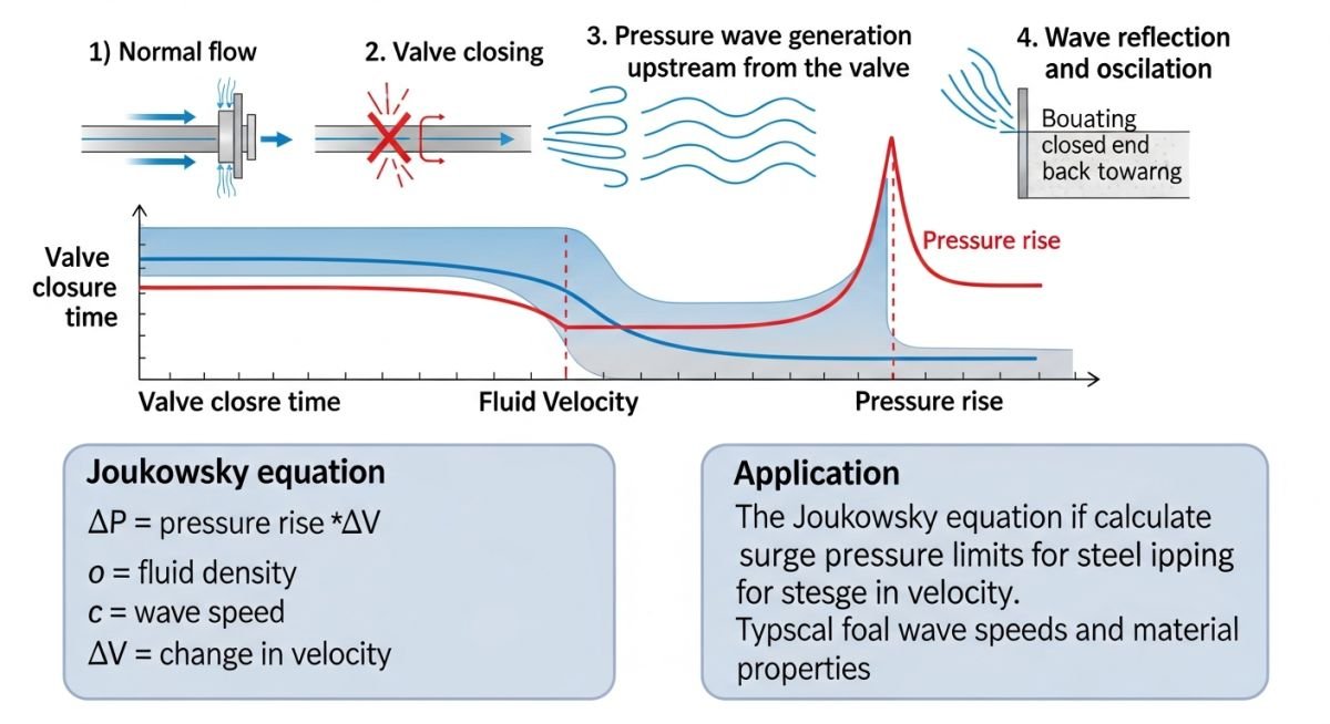
Calculating Wave Speed and Surge Magnitude
To calculate the wave speed ‘a’, we use the formula: a equals the square root of (K divided by rho) divided by the square root of (1 plus (K/E) times (D/t) times c). In this expression, K is the fluid bulk modulus, E is the pipe material modulus of elasticity, D is the pipe internal diameter, and t is the wall thickness. The constant ‘c’ accounts for the pipe support conditions.
Field Warning: The “Rigid Pipe” Fallacy
Many junior engineers assume that thicker pipe walls always reduce surge pressure. While increasing wall thickness ‘t’ does lower the wave speed slightly, it also increases the pipe’s stiffness, which can actually lead to higher peak pressures in certain high-velocity systems. Always perform a full transient analysis using software like AFT Impulse or similar tools for complex networks.
Once you have the wave speed, you must compare the calculated surge pressure against the pipe’s pressure rating. Under ASME B31.3, you are permitted to exceed the design pressure by a specific percentage during occasional transient events, provided the total stress does not exceed the yield strength of the material. However, relying on this allowance for routine operations is a recipe for fatigue failure.
Effective mitigation requires managing the time of valve closure. If the valve closure time is greater than the round-trip wave travel time (2L/a), the surge is considered “slow” and the pressure rise is significantly attenuated. If the closure is faster, you face the full force of the Joukowsky shockwave. I always recommend installing slow-closing check valves or surge anticipator valves in any system where the fluid velocity exceeds 2 meters per second.
Surge Mitigation Strategy Evaluation: This assessment compares the operational benefits of active surge control systems against the inherent mechanical complexities and maintenance requirements of high-pressure piping networks.
Advantages of Proactive Mitigation
- Extends the fatigue life of pump seals and mechanical couplings.
- Prevents catastrophic rupture of thin-walled piping sections.
- Reduces noise pollution and vibration-induced structural damage.
- Ensures compliance with safety standards like ASME B31.3.
- Minimizes downtime associated with emergency pipe repairs.
Disadvantages of Complex Systems
- High initial capital expenditure for surge relief valves.
- Increased maintenance frequency for accumulators and bladders.
- Potential for “false trips” if sensors are not calibrated.
- Added complexity in control logic for automated pump stations.
- Risk of secondary surges if relief valves are undersized.
Industrial Fluid Management Applications: These scenarios demonstrate the critical necessity of transient analysis in high-velocity pumping environments where fluid momentum poses a constant threat to system integrity.
Municipal Water Distribution Networks
In large-scale municipal water systems, long-distance transmission lines are highly susceptible to water hammer during power outages. Engineers must install surge tanks at high-elevation points to provide a buffer for the returning pressure wave, effectively decoupling the pump station from the main pipeline inertia.
Petrochemical Refinery Feedstock Transfer
Refineries often handle volatile hydrocarbons where even a minor surge can lead to seal failure and hazardous leaks. By utilizing variable frequency drives (VFDs) to ramp down pump speeds gradually, we can eliminate the sudden velocity changes that trigger destructive pressure spikes in high-pressure transfer lines.
Industrial Cooling Water Systems
Large cooling towers rely on massive pump arrays that, when cycled, create significant transient loads on the return piping. Implementing slow-closing butterfly valves with hydraulic dampeners ensures that the kinetic energy is dissipated over a longer time interval, protecting the heat exchanger integrity.
When evaluating water hammer basics in pumps, engineers must quantify the pressure rise resulting from rapid flow velocity changes. The following table outlines the critical variables and their typical ranges encountered during transient analysis in industrial piping systems. These parameters are essential for determining the peak surge pressure, which must be compared against the allowable pressure ratings defined in ASME B31.3.
Understanding these variables allows for the selection of appropriate surge protection devices, such as pressure relief valves or surge tanks. Note that the wave speed is highly dependent on the pipe material’s modulus of elasticity and the fluid’s bulk modulus, which can vary significantly with temperature and entrained air content.
| Parameter | Symbol | Typical Units | Engineering Significance |
|---|---|---|---|
| Wave Speed | a | m/s | Determines the speed of the pressure wave propagation. |
| Flow Velocity Change | delta v | m/s | Primary driver of the magnitude of the surge. |
| Fluid Density | rho | kg/m3 | Influences the kinetic energy of the fluid column. |
| Pipe Wall Thickness | t | mm | Affects pipe elasticity and wave speed calculation. |
Always ensure that the calculated peak pressure, including the surge component, does not exceed 133% of the pipe’s pressure rating during occasional events, as permitted by standard design codes for short-duration transients.
This matrix provides a structured overview of the technical entities involved in transient hydraulic analysis. By mapping these components to their respective standards and physical properties, engineers can maintain consistency across complex piping projects. Proper documentation of these entities is a requirement for API 610 pump compliance and general system safety audits.
The matrix below serves as a reference for identifying which components contribute most significantly to system inertia and pressure wave reflection. When performing a sensitivity analysis, focus on the variables marked with high impact on the Joukowsky equation results.
| Entity | Standard | Function |
|---|---|---|
| Check Valve | API 594 | Prevents reverse flow and mitigates slam. |
| Surge Tank | ASME VIII | Absorbs pressure energy via gas compression. |
| Pressure Relief | API 520 | Limits peak pressure to safe design levels. |
Utilizing this matrix during the design phase ensures that all protective equipment is sized correctly for the specific fluid properties and pump discharge characteristics of your installation.
System Integrity Verification: Before commissioning any high-pressure pumping system, it is mandatory to verify the mechanical and hydraulic configuration against the design basis. This checklist ensures that the fundamental principles of water hammer mitigation are physically implemented on-site.
-
☐
Confirm check valve closure time matches the transient analysis model to prevent slamming. -
☐
Verify that all pipe supports are installed per the stress analysis report to handle dynamic loads. -
☐
Check that air release valves are positioned at high points to prevent air pocket accumulation. -
☐
Validate that pressure relief valves are calibrated to the correct set pressure as per API 520. -
☐
Inspect pump discharge piping for signs of vibration or loose flange connections during startup.
Site verification is not merely a final step but a continuous process of ensuring that the installed hardware matches the theoretical assumptions. If the actual pipe length or fluid density deviates from the design, the surge pressure calculation must be re-run to ensure the system remains within the safety margins defined by ASME B31.3. Always document any field deviations in the final as-built piping documentation for future maintenance reference.
Problem: Severe Pipe Vibration and Flange Leaks
A high-head water pumping station experienced recurring flange leaks and pipe support failures during emergency pump shutdowns.
- Rapid closure of standard swing check valves causing significant pressure spikes.
- Lack of surge protection devices in the discharge header.
- Pipe supports were designed for static loads only, ignoring dynamic surge forces.
- Fluid velocity exceeded 3.5 meters per second, exacerbating the surge magnitude.
Outcome: System Stabilization and Reliability
The implementation of a comprehensive surge mitigation strategy successfully eliminated the structural failures and leaks.
- Replacement of swing check valves with non-slam, spring-assisted check valves.
- Installation of a bladder-type surge tank to dampen pressure oscillations.
- Retrofitting of pipe supports with hydraulic snubbers to absorb dynamic energy.
- Reduction of peak surge pressure by 65 percent, verified through field pressure transducers.
My recommendation for similar systems is to prioritize the installation of non-slam check valves at the design stage. Retrofitting is significantly more expensive and requires extensive downtime compared to integrating surge protection during the initial construction phase.
Frequently Asked Engineering Questions
What is the Joukowsky equation used for?
- It provides a conservative estimate for peak pressure in rigid pipe systems.
- Engineers use it to determine if the pipe wall thickness meets ASME B31.3 requirements.
- It assumes an instantaneous valve closure, which is the worst-case scenario for surge generation.
How do non-slam check valves mitigate water hammer?
- They utilize internal springs to assist in rapid closure during pump deceleration.
- By closing at the moment of zero velocity, they eliminate the slamming effect common in swing check valves.
- These valves are essential for protecting high-head pumps from reverse flow damage.
Why is air in the piping system dangerous?
- Air pockets can compress and expand rapidly, causing secondary pressure oscillations.
- They reduce the effective cross-sectional area of the pipe, increasing local flow velocity.
- Proper installation of air release valves at high points is required to maintain hydraulic design integrity.
What role does pipe elasticity play in surge?
- The modulus of elasticity of the pipe material is a key variable in the wave speed calculation.
- Thinner pipe walls increase the elasticity, potentially lowering the surge pressure.
- Engineers must balance pipe wall thickness for both pressure containment and surge mitigation.
How do surge tanks protect pump systems?
- They provide a buffer that slows down the rate of pressure change in the system.
- These tanks are sized based on the total volume of fluid and the expected transient flow rate.
- Regular maintenance of the gas pre-charge pressure is required to ensure the tank remains effective.
Are there specific standards for surge analysis?
- ASME B31.3 defines the allowable pressure limits for occasional events.
- API 610 specifies the requirements for pump performance and reliability under transient conditions.
- Industry best practices often involve using specialized hydraulic modeling software to simulate complex piping networks.
📚 Recommended Resources: Water Hammer Basics in Pumps
Complete Course on
Piping Engineering
Check Now
Key Features
- 125+ Hours Content
- 500+ Recorded Lectures
- 20+ Years Exp.
- Lifetime Access
Coverage
- Codes & Standards
- Layouts & Design
- Material Eng.
- Stress Analysis
