Valve Inspection & Testing: Mastering API 598 Standards
In my two decades of field experience, I have seen that the most catastrophic piping failures often trace back to a single, overlooked valve defect. Whether you are managing a greenfield refinery project or performing a turnaround, understanding the nuances of Valve Inspection and Testing is non-negotiable. We are not just checking boxes; we are validating the primary barrier between hazardous process fluids and the environment.
This guide dissects the API 598 standard, moving beyond the basic pass-fail criteria to explore the technical depth required for third-party verification. We will cover hydrostatic shell tests, high-pressure closure tests, and the critical seat leakage rates that determine whether a valve is truly fit for service.
Key Takeaways for Engineers:
- Mastering the specific pressure hold times required by API 598.
- Identifying the difference between shell integrity and seat tightness testing.
- Implementing third-party inspection protocols to mitigate supply chain quality risks.
- Understanding the impact of test fluid temperature on leakage measurement accuracy.
Technical Deep-Dive: Valve Inspection and Testing Protocols
Valve Inspection and Testing: The systematic application of hydrostatic and pneumatic pressure tests to confirm that valve components meet the design pressure-temperature ratings and leakage tolerances specified in API 598.
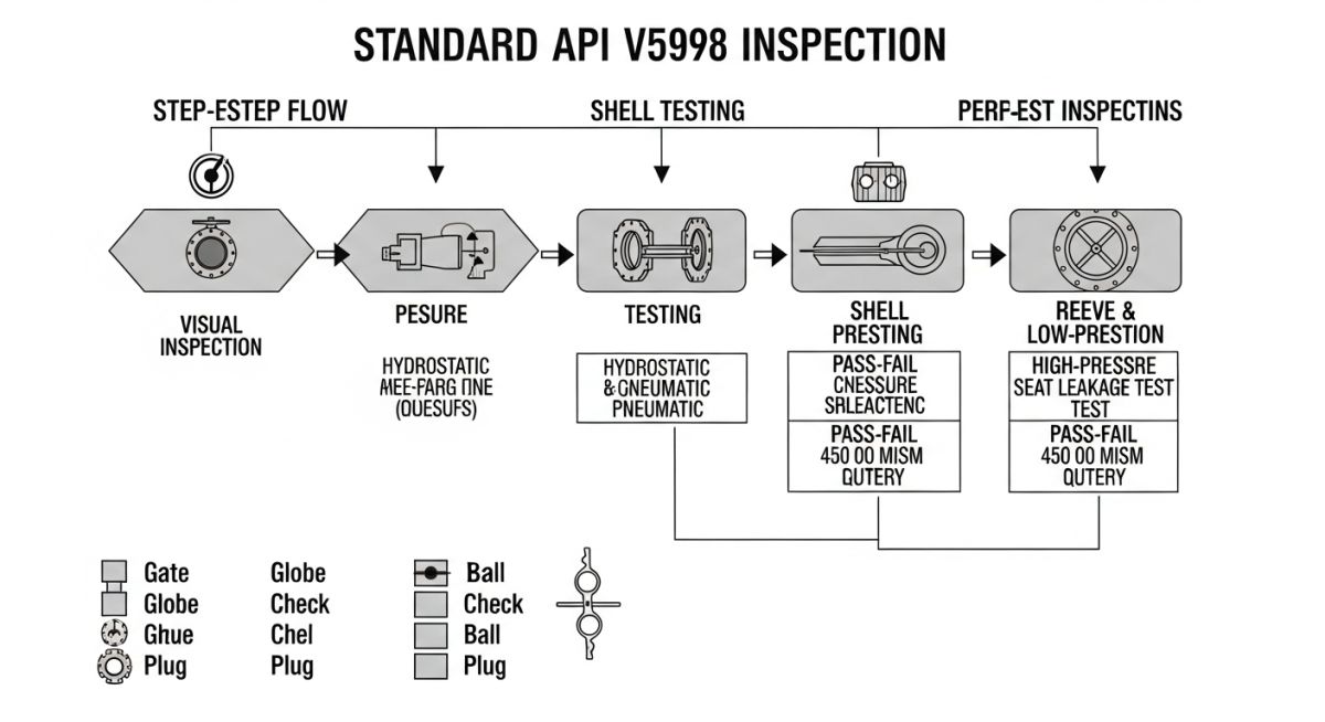
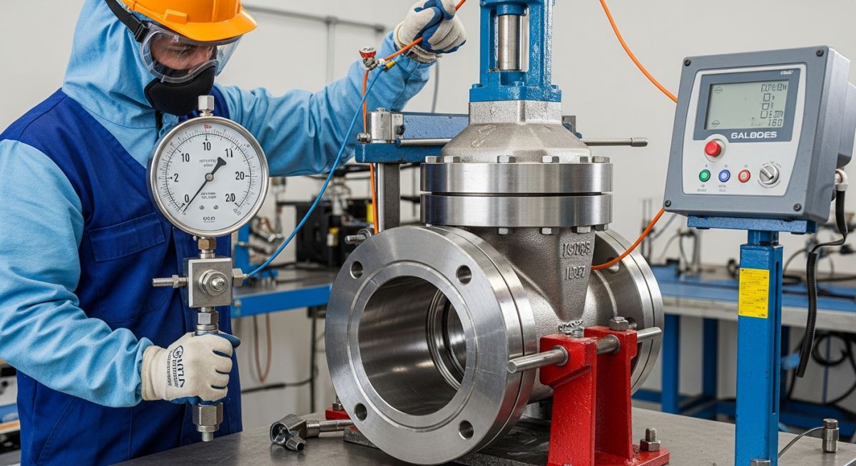
The core of API 598 lies in the distinction between shell testing and closure testing. The shell test is designed to verify the pressure-retaining capability of the valve body, bonnet, and packing gland. I typically require a test pressure of 1.5 times the maximum allowable pressure at 38 degrees Celsius. Any visible leakage through the pressure boundary during this phase is an immediate cause for rejection.
Closure testing, however, is more nuanced. It evaluates the seat’s ability to prevent fluid migration across the valve when in the closed position. For metal-seated valves, we must account for the allowable leakage rates defined in Table 5 of the standard. These rates are not zero; they are calculated based on the nominal pipe size and the test medium. If you are testing a 6-inch gate valve, the allowable leakage is significantly different than for a 2-inch ball valve.
Field Warning: Test Fluid Contamination
Never use untreated water for hydrostatic testing of stainless steel valves. Chlorides in the water can induce stress corrosion cracking, which may not manifest until months after the valve is installed. Always verify the chloride content of your test medium is below 50 ppm, or use demineralized water with an appropriate corrosion inhibitor.
When performing third-party inspections, I focus heavily on the calibration of the pressure gauges. API 598 mandates that gauges must be calibrated within the last 12 months. Furthermore, the gauge range should be selected such that the test pressure falls within the middle 50 percent of the scale. This ensures the highest accuracy and readability during the hold period.
The hold time is another critical parameter. For valves up to 2 inches, the minimum hold time for both shell and closure tests is 15 seconds. As the valve size increases, this duration extends to 60 seconds or more for valves 18 inches and larger. I have seen many inspectors rush these hold times, leading to missed micro-leaks that only appear under sustained pressure.
Finally, consider the orientation of the valve during testing. For check valves, the test must be performed in the direction of flow. For double-block-and-bleed valves, the cavity must be vented to ensure that pressure is not trapped, which could provide a false positive for seat tightness. These technical details are what separate a compliant valve from a potential site failure.
Standardized Testing Benefits: The implementation of API 598 provides a uniform benchmark for quality, ensuring that valves from different manufacturers meet identical safety and performance thresholds.
Advantages
- Provides a globally recognized, objective pass-fail criteria for procurement.
- Reduces the risk of catastrophic pressure boundary failure during commissioning.
- Ensures seat tightness, preventing process fluid loss and environmental contamination.
- Facilitates easier interchangeability of valves across different project sites.
- Validates the structural integrity of casting and welding processes.
Disadvantages
- Testing adds significant lead time to the procurement schedule.
- High-pressure testing equipment requires substantial capital investment and maintenance.
- Improper test fluid management can lead to internal corrosion or contamination.
- Does not account for long-term wear or cyclic fatigue in service.
- Requires highly skilled personnel to interpret results and identify subtle leaks.
Industrial Valve Deployment: The application of API 598 testing is critical across high-consequence sectors where pressure containment is the primary safety objective.
Refinery Hydrocarbon Processing
In crude distillation units, valves are subjected to extreme thermal cycling and corrosive media. Rigorous API 598 testing ensures that gate and ball valves maintain seal integrity despite the presence of hydrogen sulfide and other aggressive compounds.
High-Pressure Steam Generation
Power plant boiler feed systems rely on check and globe valves to prevent backflow and maintain pressure. Testing these components under API 598 protocols prevents steam leaks that could lead to thermal erosion of piping supports and structural damage.
Cryogenic Liquefied Natural Gas (LNG)
LNG facilities operate at temperatures as low as minus 162 degrees Celsius. Testing valves for these applications requires specialized API 598 procedures to ensure that seat materials do not become brittle and fail to seal under extreme thermal contraction.
Chemical Storage and Distribution
For hazardous chemical storage, the environmental impact of a valve leak is severe. Third-party verification of valve seat tightness using API 598 standards provides the necessary assurance that containment systems will function correctly during emergency shutdowns.
When executing valve inspection and testing, the pressure parameters defined by API 598 serve as the definitive baseline for verifying pressure boundary integrity. These values are not merely suggestions but are critical thresholds that determine whether a valve is fit for high-pressure hydrocarbon service or must be rejected due to casting porosity or seat deformation.
The following table outlines the standard test pressures for shell and seat testing based on the valve’s nominal pressure class. Engineers must ensure that test gauges are calibrated within the last six months and that the test medium—typically water, air, or inert gas—is compatible with the valve trim materials to prevent internal corrosion or chemical degradation during the testing cycle.
| Pressure Class | Shell Test (PSI) | Seat Test (PSI) | Test Duration (Min) |
|---|---|---|---|
| 150 | 425 | 315 | 2 |
| 300 | 1100 | 815 | 2 |
| 600 | 2175 | 1600 | 3 |
Always verify that the test duration is strictly maintained. Short-cutting the hold time is a common failure point in third-party inspections, as it allows micro-leaks that only manifest under sustained stress to go undetected until the valve is installed in the field.
Effective quality assurance in valve procurement requires a deep understanding of the relationship between international standards and physical valve components. This matrix maps the critical entities involved in the inspection process, linking specific valve parts to their corresponding testing requirements and the governing ASME or API standards.
By utilizing this matrix, inspectors can quickly identify which standard governs a specific component, such as the stem packing or the seat-to-disc interface. This systematic approach reduces ambiguity during third-party audits and ensures that all documentation—from Mill Test Reports to final inspection certificates—aligns with project-specific piping specifications.
| Component | Standard | Inspection Focus |
|---|---|---|
| Valve Body | API 598 | Shell Integrity/Porosity |
| Seat/Disc | API 598 | Leakage Rate/Seating Force |
| Stem/Packing | API 622 | Fugitive Emission Compliance |
Maintaining this matrix as part of your project quality plan ensures that every valve is tracked from the foundry to the final installation point, providing a robust audit trail for safety-critical systems.
Valve Inspection and Testing requires a disciplined approach to site verification. Before any pressure is applied, the inspector must confirm that the valve is correctly oriented, the test bench is calibrated, and the safety protocols are fully operational. This checklist serves as a mandatory guide for field engineers to ensure compliance with API 598 requirements.
- Calibration Check: Verify that all pressure gauges are within their valid calibration window (typically 6 months) and have a range that covers 1.5 to 4 times the test pressure.
- Visual Inspection: Inspect the valve body for casting defects, cracks, or improper markings that deviate from the ASME B16.34 requirements.
- Medium Compatibility: Confirm the test medium (water, air, or nitrogen) is clean and free of contaminants that could damage the seat or internal trim.
- Safety Barrier: Ensure the test area is cordoned off and that all personnel are wearing appropriate PPE, as high-pressure testing poses significant kinetic energy risks.
- Documentation Review: Cross-reference the valve serial number with the manufacturer’s Material Test Report (MTR) to ensure material traceability.
Failure to complete these steps can lead to catastrophic failure during the hydrostatic test. Always document the results of each check in the inspection log, as this data is essential for the final project turnover package and long-term asset integrity management.
The Problem: Premature Seat Leakage in High-Pressure Service
- A batch of 12-inch gate valves failed the seat leakage test during a third-party inspection at the manufacturer’s facility.
- The valves were intended for a high-pressure natural gas pipeline, requiring strict adherence to API 598.
- Contributing factors included improper seat lapping techniques and the use of non-conforming seal materials that did not match the project specifications.
- The leakage rates exceeded the allowable limits, indicating a fundamental failure in the manufacturer’s quality control process.
The Outcome: Corrective Action and Successful Re-Testing
- The manufacturer was required to perform a full teardown and inspection of the seat-to-disc interface.
- We mandated a re-lapping process using precision-grade diamond paste to achieve the required surface finish.
- All seals were replaced with materials verified against the project’s material compatibility matrix.
- Upon re-testing, all valves passed the API 598 criteria, resulting in zero leakage during the final witness test.
This case highlights the importance of third-party intervention. Without rigorous inspection, these valves would have been installed in the field, leading to costly downtime and potential environmental hazards due to fugitive emissions.
Frequently Asked Engineering Questions
What is the primary difference between shell and seat testing?
- Shell testing is performed with the valve in a partially open position to ensure all internal cavities are pressurized.
- Seat testing is performed with the valve fully closed, applying pressure to one side of the disc to measure leakage rates.
- Both tests are mandatory under API 598 to ensure total system integrity.
How do I determine the correct test duration?
- For valves up to 2 inches, the minimum duration is typically 15 seconds.
- For valves between 2.5 and 8 inches, the duration increases to 60 seconds.
- For valves 10 inches and larger, the duration is at least 120 seconds.
- Always consult the latest edition of the standard, as these requirements can change based on the valve type and service conditions.
Can I use air for hydrostatic testing?
- Hydrostatic testing (using water) is the preferred method for shell integrity because water is incompressible.
- If pneumatic testing is required, it must be performed behind a blast shield with strict safety protocols.
- Always verify the test medium requirements in the project specification before starting the test.
What is the role of a third-party inspector?
- They witness the actual testing process to ensure no steps are skipped.
- They verify the calibration of all test equipment used during the inspection.
- They review and sign off on the final test reports, providing a layer of accountability that is essential for high-risk industrial projects.
What happens if a valve fails the test?
- Repairs must be documented and approved by the project engineer before any re-testing occurs.
- After repairs, the valve must undergo the full suite of tests again to ensure the fix was successful.
- Repeated failures often indicate a systemic issue with the manufacturer’s quality management system, which may require a formal audit.
How do I ensure material traceability?
- Always verify that the heat number on the valve matches the documentation provided by the manufacturer.
- Ensure that the MTR includes chemical composition and mechanical property data that meets the requirements of ASME standards.
- If the documentation is missing or incomplete, the valve should be rejected, as its material integrity cannot be guaranteed.
📚 Recommended Resources: Valve Inspection and Testing
Read these Guides
- 📄 Pressure Vessel Design: Engineering Standards, Materials, and Support Systems
- 📄 Strategic Location of Static Equipment: Fired Heaters, Reactors, and Drums
- 📄 Pressure Vessel Design: Mastering Pressure and Temperature Safety Limits
- 📄 Understanding Acoustic-Induced Vibration: A Guide for Piping Engineers
🎓 Advanced Training


Complete Course on
Piping Engineering
Check Now
Key Features
- 125+ Hours Content
- 500+ Recorded Lectures
- 20+ Years Exp.
- Lifetime Access
Coverage
- Codes & Standards
- Layouts & Design
- Material Eng.
- Stress Analysis
