Table of Contents
Mastering the Core Types of Pipe Joints in Industrial Piping
In my 20+ years of piping engineering, I have seen projects succeed or fail based on a single, seemingly minor decision: selecting the wrong connection method. A piping system is only as robust as its weakest link. When you are routing high-pressure hydrocarbons, superheated steam, or corrosive chemicals, understanding the nuances of different connection methods is not just academic—it is a fundamental safety requirement.
Each connection method has a specific operating envelope. A joint that performs flawlessly in a low-pressure utility water line can fail catastrophically within hours if subjected to thermal cycling or severe vibration. Throughout my career, I have analyzed joint failures ranging from crevice corrosion in socket welds to gasket blowouts on poorly aligned flanges. This guide shares the practical, field-tested engineering insights required to make the right selection every single time.
Key Engineering Takeaways
- Welded Joints offer the highest pressure-temperature ratings and are the industry standard for critical, non-destructive testing (NDT) verified lines.
- Flanged Connections provide unmatched accessibility for maintenance and cleaning but introduce potential leak paths and require precise torque management.
- Threaded and Socket Joints are highly cost-effective for small-bore piping but carry strict limitations regarding cyclic stress and corrosive environments.
- Code Compliance with ASME B31.3 dictates the selection, inspection, and testing protocols for every joint type.
Complete Course on
Piping Engineering
Check Now
Key Features
- 125+ Hours Content
- 500+ Recorded Lectures
- 20+ Years Exp.
- Lifetime Access
Coverage
- Codes & Standards
- Layouts & Design
- Material Eng.
- Stress Analysis
How to Select the Right Types of Pipe Joints
When designing a piping system, joint selection directly influences the required wall thickness, material costs, and non-destructive examination (NDE) scope. Let us break down the primary joint categories used in heavy industrial applications.
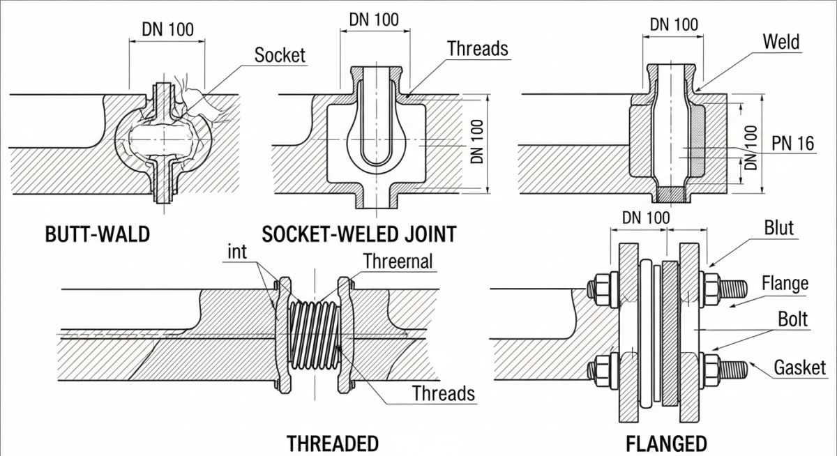
1. Butt-Welded Joints
Butt-welding is the gold standard for high-pressure, high-temperature piping. The pipe ends are prepared with a bevel (typically 37.5 degrees per ASME B16.25) and fused together. This creates a continuous, full-penetration weld that matches or exceeds the strength of the parent pipe.
In my experience, butt-welds are preferred for all lines 2 inches and larger in hydrocarbon and steam service. They offer a smooth internal profile, minimizing turbulence and pressure drop. The joint efficiency factor (E) for a 100% radiographed butt-weld is 1.00, allowing for optimized wall thickness calculations.
2. Socket-Welded Joints
Socket welding involves inserting a plain-end pipe into a recessed area of a fitting or valve and applying a fillet weld around the outer diameter. This joint is primarily used for small-bore piping (typically 1.5 inches and smaller).
While easier to align than butt-welds, socket welds have a built-in vulnerability: the expansion gap. ASME B31.3 requires a 1/16-inch (1.5 mm) gap at the bottom of the socket before welding to allow for thermal expansion. If the welder bottoms out the pipe, the weld root will experience extreme stress during thermal cycles, leading to cracking.
In my field audits, I have frequently discovered severe crevice corrosion inside socket-welded joints. The inherent gap between the pipe OD and the socket ID acts as a stagnant zone where corrosive fluids, chlorides, or moisture accumulate. Avoid socket welds in highly corrosive services, sour services (H2S), or severe cyclic services.
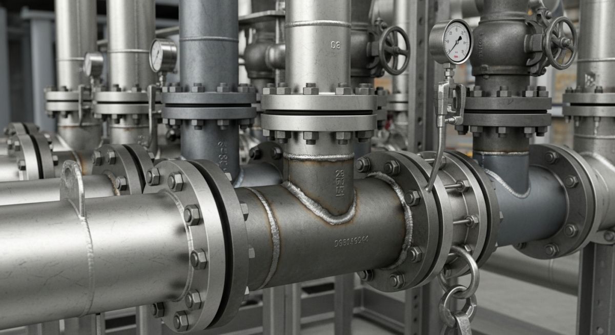
3. Flanged Joints
Flanged joints are mechanical connections consisting of two flanges, a gasket, and bolting. They are designed according to ASME B16.5 (up to 24 inches) and ASME B16.47 (26 inches and larger).
The primary advantage of flanged joints is disassembly. They are required at connections to pumps, control valves, vessels, and any piping spool that must be removed regularly for cleaning or inspection. However, they are heavy, expensive, and represent a potential leak path if the bolts are not torqued using a calibrated, cross-pattern procedure.
4. Threaded Joints
Threaded joints utilize tapered pipe threads (NPT per ASME B1.20.1) to create a mechanical seal, often supplemented with thread sealant or Teflon tape. They are restricted to low-pressure, non-hazardous, small-bore utility lines (such as instrument air or potable water).
The major engineering drawback of threaded joints is that the thread cutting process reduces the effective wall thickness of the pipe. This reduction must be accounted for in the pressure design calculations by adding a thread depth allowance (typically 1.2 mm to 2.0 mm depending on pitch) to the minimum required wall thickness.
ASME B31.3 Pressure Design Calculations
To illustrate how joint selection affects pipe design, let us look at the ASME B31.3 wall thickness formula:
Where:
- t = Pressure design thickness (inches/mm)
- P = Internal design gage pressure (psi/MPa)
- D = Outside diameter of the pipe (inches/mm)
- S = Allowable stress value for the material at design temperature
- E = Quality factor or joint efficiency (ranges from 0.60 to 1.00)
- W = Weld joint strength reduction factor
- Y = Coefficient from Table 304.1.1
Notice how the joint efficiency factor (E) sits in the denominator. If you select a seamless pipe with a butt-welded joint (E = 1.00), the required wall thickness is minimized. If you select a longitudinal welded pipe with no radiography (E = 0.85 or 0.70), the required wall thickness increases significantly to compensate for the lower joint reliability. This demonstrates how joint selection directly impacts material weight and overall project cost.
Comparing Performance of Different Types of Pipe Joints
The table below provides a direct comparison of the primary joint types used in industrial process plants. Use this matrix during the front-end engineering design (FEED) phase to align your piping specifications with process conditions.
| Joint Type | ASME Standard | Pressure Rating | Temperature Limits | Primary Application | NDT Requirement |
|---|---|---|---|---|---|
| Butt-Weld | ASME B16.9 | Unlimited (Matches Pipe) | Cryogenic to High Temp (>1000°F) | Process lines, high pressure steam, hydrocarbons | Radiography (RT) or Ultrasonic (UT) |
| Socket-Weld | ASME B16.11 | Class 3000, 6000, 9000 | Moderate (-20°F to 800°F) | Small-bore process lines, lube oil, vents/drains | Magnetic Particle (MT) or Dye Penetrant (PT) |
| Flanged | ASME B16.5 | Class 150 to 2500 | Limited by gasket material | Equipment connections, maintenance spools | Visual (VT) and gasket seating checks |
| Threaded | ASME B1.20.1 | Low (Typically < 300 psi) | Low Temp (< 400°F) | Instrument air, utility water, nitrogen | Visual (VT) and bubble leak testing |
Technical Mapping & Specifications Matrix
To ensure seamless integration with procurement and construction teams, use this mapping matrix to align joint types with their corresponding physical parameters and standard references.
| Entity / Acronym | Technical Definition | Physical Parameter Impact | Applicable Standard |
|---|---|---|---|
| NPS | Nominal Pipe Size | Determines joint selection boundary (small-bore vs. large-bore) | ASME B36.10M |
| RTJ | Ring Type Joint | High-pressure flanged sealing using metal rings in grooves | ASME B16.20 |
| HAZ | Heat Affected Zone | Area adjacent to weld joint susceptible to metallurgical changes | AWS D10.10 |
| NPT | National Pipe Thread | Tapered thread profile providing mechanical seal via interference | ASME B1.20.1 |
Field Inspection Checklist for Piping Joints
No matter how perfect your design is on paper, the joint must be executed correctly in the field. Below is the checklist I use during site audits to verify joint integrity before hydrostatic testing.
Pre-Commissioning Verification Checklist
-
Butt-Weld Fit-Up Verification: Confirm root gap (typically 1.6 to 3.2 mm) and alignment (hi-lo mismatch less than 1.6 mm) before welding begins.
-
Socket Weld Expansion Gap: Verify that the 1/16-inch (1.5 mm) gap is maintained using scribe marks or gap-o-let rings prior to fillet welding.
-
Flange Alignment Check: Ensure flange faces are parallel within 0.5 mm/m and bolt holes align without forcing the pipe.
-
Gasket Verification: Confirm that the gasket material, rating, and dimensions match the piping specification (e.g., spiral wound per ASME B16.20).
-
Torque Management: Verify that bolts are lubricated and torqued in a minimum of three progressive stages (30%, 60%, 100%) using a calibrated torque wrench.
-
Thread Engagement: Ensure a minimum of 2 to 3 threads remain exposed past the fitting after tightening to guarantee full thread engagement.
Field Case Study: Real-World Application
The Problem: Recurring Failures in a Hydrocarbon Line
At a refinery in 2022, a 1.5-inch hydrocarbon line operating at 450 psi and 350°F experienced repeated failures at the socket-welded elbow joints. The plant was experiencing shutdowns every six months due to pinhole leaks.
Upon metallurgical analysis of the failed joints, we discovered two issues: first, the welders had failed to leave the required 1/16-inch expansion gap, causing thermal stress cracking at the weld root. Second, the fluid contained trace amounts of wet H2S, which accumulated in the stagnant crevice of the socket, accelerating localized crevice corrosion.
The Outcome: Redesign and Material Optimization
I recommended replacing all socket-welded fittings in this service with butt-welded fittings. Although butt-welding 1.5-inch pipe is more labor-intensive and requires highly skilled welders, it completely eliminated the internal crevice.
We specified 100% radiography for the new butt-welds, raising the joint efficiency factor (E) to 1.00. Over the past four years, this line has operated continuously without a single leak, saving the operator an estimated 240,000 in unscheduled downtime and maintenance costs.
Direct Recommendation: Never use socket welds in sour service (H2S) or highly cyclic thermal environments, regardless of pipe size. Always default to butt-welds or high-integrity flanged connections for these critical services.
Frequently Asked Engineering Questions
What is the difference between a socket weld and a butt weld joint?
When should threaded pipe joints be avoided in industrial piping?
How does ASME B31.3 govern the selection of flanged joints?
What are the limitations of slip-on flanges compared to weld neck flanges?
Why are expansion joints used instead of rigid pipe joints?
How does joint efficiency affect pipe wall thickness calculations?

📚 Recommended Resources: Types of Pipe Joints
Read these Guides


Related posts:
![CNC rotary draw tube bending machine shaping a stainless steel pipe in a manufacturing facility.]()
What is Tube Bending? Working, Types, and Industrial Applications
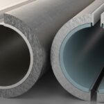
![Cross-section comparison of a metallurgically bonded clad pipe and a mechanically bonded lined pipe.]()
What is Cladded Pipe? Difference Between Clad and Lined Pipe
![Conceptual illustration of digital technical data exchange between an engineering office and a process equipment vendor.]()
How to Manage Technical Information Exchange With Process Equipment Vendors
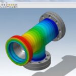
![3D piping stress analysis of a Smart Tee model in START-PROF software.]()
Mastering Smart Tee Model Considerations in START-PROF Stress Analysis
![Modern industrial compressed air system installation with rotary screw compressors and receiver tanks in a clean facility.]()
Designing a Compressed Air System for Maximum Industrial Efficiency
![Coated industrial bolts on an offshore pipeline flange showing corrosion protection.]()
Coating Selection for External Bolting to Reduce Corrosion in Piping