What is Temporary Pipe Support and Why We Need Them
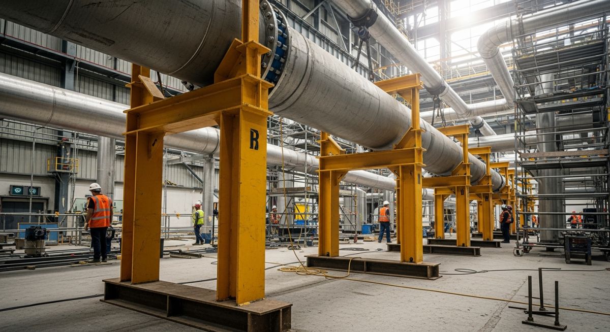
In my 20-plus years of managing piping stress analysis and field construction, I have seen many projects suffer from unexpected piping failures. Often, these failures do not happen during normal operations. Instead, they occur during construction, hydrotesting, or maintenance. Field crews sometimes treat temporary supports as an afterthought, using scrap wood, unrated structural steel, or random scaffolding. This is a dangerous practice.
When you remove a control valve for servicing or fill a large-diameter gas line with water for a hydrotest, the load profile of your piping system changes completely. Without engineered temporary supports, the piping will sag, flanges will misalign, and inline equipment will experience severe nozzle loads. This guide explains the engineering principles, load calculations, and field practices needed to design and install these temporary systems safely.
Key Engineering Takeaways
- Understand how hydrotest water loads can exceed operating gas loads by over 300 percent.
- Learn to calculate maximum allowable spans for temporary piping configurations.
- Identify the correct structural steel profiles for temporary load paths.
- Discover how to prevent flange misalignment during valve and equipment maintenance.
Understanding Temporary Pipe Support Design and Functions
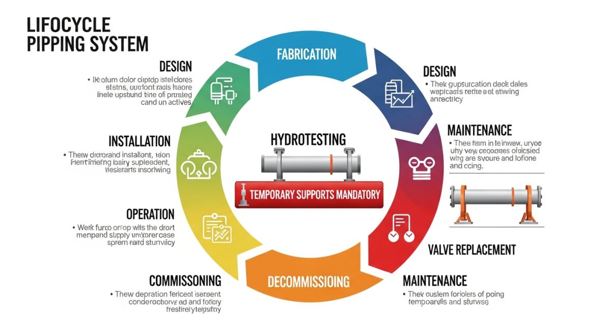
When designing a temporary support, we must evaluate the temporary state of the piping system. This state is often very different from the final operating condition. For example, during a hydrotest, a vapor line is filled with water. Because water is much heavier than vapor, the weight of the system increases dramatically. If the permanent supports were designed only for the vapor load, they will fail under the hydrotest load.
To prevent this, we must calculate the temporary hydrotest load and place temporary supports at strategic locations. The basic formula to calculate the total weight of the piping system during a hydrotest is:
Where the water weight is calculated based on the internal volume of the pipe:
Once we know the total unit weight (W) in Newtons per meter, we can calculate the maximum allowable span (L) to keep the bending stress within the limits allowed by ASME B31.3 Process Piping. The maximum bending stress (S) for a simply supported beam model is:
Where Z is the section modulus of the pipe. Rearranging this formula allows us to solve for the maximum allowable temporary span length:
In this calculation, the allowable stress (S) during hydrotest is typically limited to 90 percent of the material’s yield strength at ambient temperature, as specified in ASME B31.1 Power Piping and ASME B31.3.
During hydrotesting of lines supported by spring hangers, you must install travel stops (locking pins) on the springs. If you do not lock the springs, the heavy water load will bottom them out. This transfers massive, unplanned loads to the equipment nozzles and can permanently damage the spring coils.
Another common use case is during maintenance, such as replacing a heavy control valve. When you unbolt the valve, the piping on either side loses its structural continuity. Without temporary supports, the two open ends of the pipe will sag and pull apart. This makes it almost impossible to align and bolt the new valve in place without introducing severe residual stresses into the system.
When Do We Need Temporary Pipe Support Systems
To help field engineers select the right support type, I have compiled this reference table based on typical refinery and chemical plant maintenance scenarios.
| Maintenance Scenario | Primary Risk | Recommended Temporary Support | Design Load Consideration |
|---|---|---|---|
| Hydrotesting Gas Lines | Severe sagging, spring hanger damage | Rigid dummy supports, locked spring hangers | Full water weight + pipe weight |
| Control Valve Replacement | Flange misalignment, nozzle overloading | Adjustable pipe stands, temporary cradles | Asymmetric piping weight on both sides |
| Hot-Tapping Operations | Vibration, localized shell buckling | Clamped structural braces, saddle supports | Machine weight + dynamic cutting forces |
| Tie-In Modifications | Thermal expansion stress on new joints | Temporary slide plates, guide supports | Frictional resistance + thermal growth |
Technical Mapping & Specifications Matrix
This matrix maps the core technical entities, structural acronyms, and physical parameters associated with temporary piping design.
| Entity / Acronym | Technical Definition | Physical Parameter | Standard Reference |
|---|---|---|---|
| TPS | Temporary Pipe Support | Load Capacity (kN) | ASME B31.3 / MSS SP-58 |
| DL | Dead Load (Pipe + Fluid) | Weight per Unit Length (kg/m) | ASME B31.3 Section 301.2 |
| TL | Test Load (Water Filled) | Hydrostatic Force (kN) | ASME B31.3 Section 345.4 |
| MSS | Manufacturers Standardization Society | Support Materials & Design | MSS SP-58 |
Field Inspection of Temporary Pipe Support Installations
Before any hydrotest or major maintenance activity begins, the lead piping inspector must walk the line and verify the temporary supports. I have developed this checklist over years of field audits to prevent structural failures.
Field Verification Checklist
-
Load Path Verification: Ensure the temporary support transfers the load to a solid foundation (concrete slab or structural steel beam) and not to unrated grating or handrails.
-
Material Rating: Verify that all structural steel members used for temporary supports are rated (e.g., ASTM A36) and free from severe corrosion or cracks.
-
Spring Hanger Locking: Confirm that all spring hangers on the line have their travel stops installed and locked before filling the line with water.
-
Pipe Protection: Ensure that neoprene pads or Teflon slides are placed between the pipe and the temporary support to prevent scratching or localized wall thinning on stainless steel or alloy lines.
-
Removal Plan: Verify that a clear removal sequence is documented so that temporary supports are not left in place when the system goes into hot operation.
Field Case Study: Real-World Application
During a turnaround at a major gas processing plant, the maintenance crew had to replace a 24-inch Class 600 control valve. The valve weighed approximately 1,800 kilograms. The crew unbolted the valve without installing any temporary supports on the adjacent piping, assuming the permanent spring hangers would hold the line.
As soon as the valve was lifted out, the piping on both sides sagged by 35 millimeters. This caused severe flange misalignment. The crew tried to force the new valve into place using chain hoists, which cracked a nearby 2-inch small-bore branch connection and threatened to damage the main header.
My team was called to resolve the issue. We immediately halted the work and calculated the required lifting force to realign the flanges without overstressing the piping. We designed two custom temporary pipe stands using ASTM A36 structural steel channels equipped with 10-ton hydraulic jacks.
We placed these stands under the piping on both sides of the valve gap. Using the hydraulic jacks, we slowly lifted the piping back to its original elevation, monitoring the stress levels using a simplified beam model. The flanges aligned perfectly, the new valve was bolted in without force, and the cracked small-bore connection was repaired and radiographed.
This incident highlights why you must never rely on permanent spring supports during maintenance. Spring supports are designed for a specific operating load. When you change that load by removing a heavy component, the system loses its balance. Always use engineered temporary supports with adjustment capabilities, such as jacks or threaded rods, for heavy valve replacements.
Frequently Asked Engineering Questions
What is the main difference between a temporary and a permanent pipe support?
Why do we need temporary supports during hydrotesting?
Can we use wooden blocks as temporary pipe supports?
What codes govern the design of temporary pipe supports?
What happens if a temporary support is left in place during operation?
How do you calculate the load on a temporary support?
===
Complete Course on
Piping Engineering
Check Now
Key Features
- 125+ Hours Content
- 500+ Recorded Lectures
- 20+ Years Exp.
- Lifetime Access
Coverage
- Codes & Standards
- Layouts & Design
- Material Eng.
- Stress Analysis