
What is Structural Resonance and How to Mitigate It
In my 20 plus years of engineering plant structures and heavy piping systems, I have seen structural resonance turn massive steel assemblies into violently shaking hazards. It is a silent threat that remains completely invisible during static load calculations. Only when a reciprocating compressor ramps up to its operating speed, or wind sheds vortices at a specific velocity, does the structure begin to self-destruct.
Understanding how to identify, calculate, and mitigate these dynamic forces is what separates a reliable, long-term installation from an operational disaster. When the excitation frequency aligns with the natural frequency of your system, the resulting dynamic amplification can multiply static stresses by a factor of twenty or more.
Key Engineering Takeaways
- Learn the fundamental physics driving dynamic amplification and frequency matching.
- Understand how to calculate natural frequencies using stiffness and mass parameters.
- Discover the practical differences between active, passive, and semi-active damping systems.
- Master the application of Tuned Mass Dampers (TMDs) in industrial environments.
- Implement field-proven inspection protocols to catch resonance before fatigue failure occurs.
How Structural Resonance Causes Catastrophic Failures
Resonance Failure Mechanisms: Dynamic amplification occurs when structural damping is insufficient to dissipate the energy transferred by periodic forces matching the system’s natural frequencies. This leads to runaway displacement, material fatigue, and ultimate structural collapse under code-regulated load combinations.
To understand this phenomenon, we must look at the fundamental equation of motion for a single-degree-of-freedom (SDOF) system. The system behavior is governed by mass, damping, and stiffness. When an external harmonic force is applied, the response of the structure is heavily dependent on the frequency ratio, which is the excitation frequency divided by the natural frequency of the structure.
The natural frequency (fn) of a structural system is calculated using the following relationship:
Where:
• fn = Natural frequency in Hertz (Hz)
• k = Structural stiffness in Newtons per meter (N/m)
• m = Mass of the system in kilograms (kg)
When the operating frequency of a machine or an environmental force matches this natural frequency, the Dynamic Amplification Factor (DAF) spikes. The DAF is defined as:
Where:
• r = Frequency ratio (excitation frequency / natural frequency)
• zeta = Damping ratio of the structural system
If the frequency ratio (r) equals 1.0 and the damping ratio (zeta) is very low (which is typical for welded steel structures, often around 1% to 2%), the DAF can easily exceed 25. This means the actual dynamic deflection and stress are 25 times greater than the static equivalent load. This rapid accumulation of stress cycles leads to high-cycle fatigue, initiating micro-cracks at weld toes and structural connections.
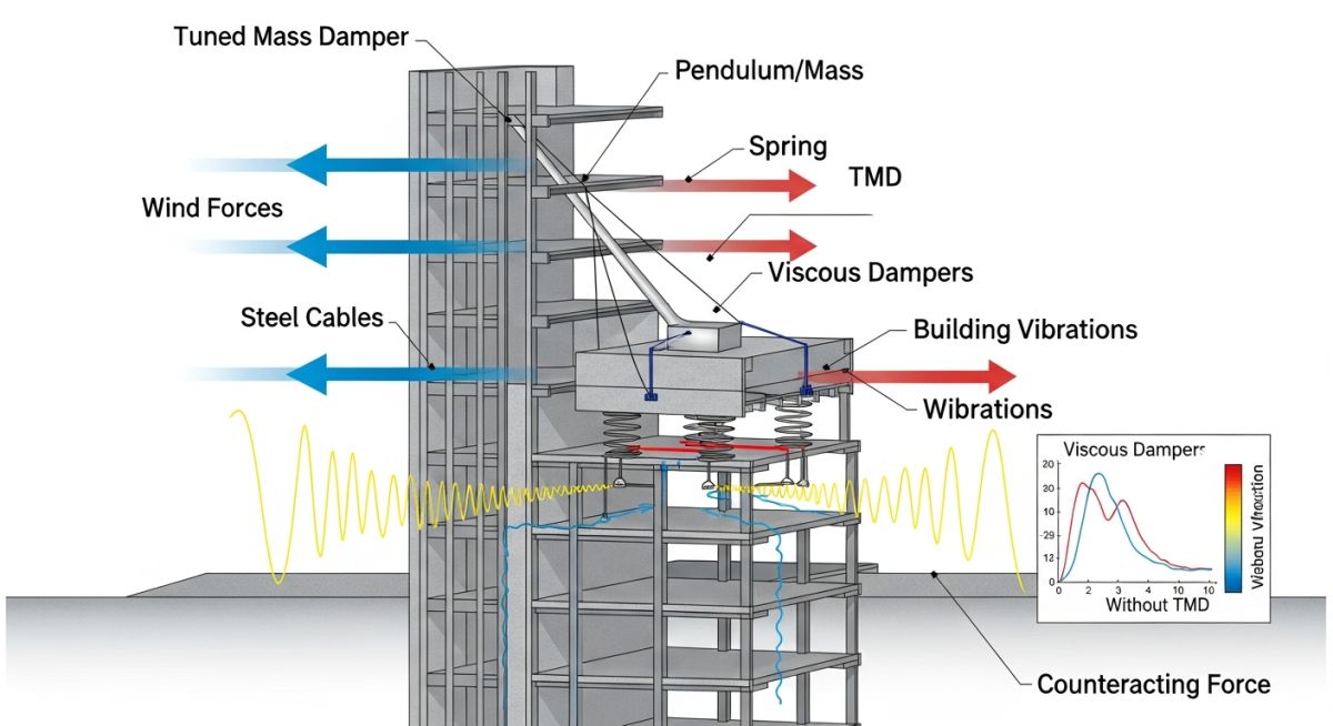
To mitigate these effects, structural engineers rely on design guidelines such as AISC Design Guide 11 (Vibrations of Steel-Framed Structural Systems) and ACI 351.3R (Foundations for Dynamic Equipment). These standards provide clear limits on allowable accelerations and amplitudes to ensure both structural integrity and human comfort.
Selecting the correct damping ratio is critical during the finite element analysis (FEA) phase. Underestimating damping leads to overly conservative and expensive designs, while overestimating it can result in structural failures. The table below outlines typical damping ratios used in industrial design according to ASCE 4-16.
| Structural Material / System Type | Typical Damping Ratio (zeta) | Applicable Design Standard | Resonance Sensitivity |
|---|---|---|---|
| Welded Steel Frames | 1.0% – 2.0% | AISC 360 | Extremely High |
| Bolted Steel Frames (High-Strength Bolts) | 3.0% – 5.0% | AISC 360 | Moderate |
| Reinforced Concrete Structures | 4.0% – 7.0% | ACI 318 | Low to Moderate |
| Prestressed Concrete Systems | 2.0% – 3.0% | ACI 318 | Moderate to High |
This matrix maps key structural dynamics parameters, their physical definitions, governing codes, and their direct impact on mitigating resonance in industrial facilities.
| Entity / Acronym | Physical Parameter | Governing Code / Reference | Mitigation Impact |
|---|---|---|---|
| TMD (Tuned Mass Damper) | Auxiliary mass, spring, and damper system tuned to a specific frequency. | ASCE 7 Chapter 13 | Reduces resonant amplitude by transferring kinetic energy to the auxiliary mass. |
| DAF (Dynamic Amplification Factor) | Ratio of dynamic displacement to static displacement. | ASCE 7 / AISC DG 11 | Indicates the severity of resonance; target design value is as close to 1.0 as possible. |
| VFD (Variable Frequency Drive) | Motor controller that varies frequency and voltage supplied to electric motors. | NEMA ICS 7.1 | Allows operators to program “skip frequencies” to avoid running equipment at resonant speeds. |
| PSD (Power Spectral Density) | Measure of signal’s power content versus frequency. | ISO 10816 | Used in random vibration analysis to identify dominant excitation frequencies. |
Field Inspection Checklist for Structural Resonance
Resonance Field Verification: Site-specific vibration assessment requires systematic measurement of structural frequencies and operating equipment speeds to identify potential frequency overlaps. This verification process ensures compliance with ISO 10816 and AISC serviceability limits.
When I perform field walkdowns on vibrating structures, I follow a strict sequence of steps to isolate the root cause. You cannot rely on visual observations alone; high-frequency micro-vibrations can cause fatigue failure without showing large visible displacements.
Step-by-Step Field Verification Checklist
Field Case Study: Real-World Application
The Problem: Piperack Vibration in a Petrochemical Plant
During the commissioning of a new reciprocating compressor unit, a multi-tier steel piperack began vibrating with displacements exceeding 12 mm at the top level. The compressor operated at a constant speed of 420 RPM (7.0 Hz).
The dynamic forces were transferring through the piping hangers directly into the structural steel. Within 48 hours of operation, small-bore piping connections began to fail due to fatigue, forcing an emergency shutdown of the process unit.
The Outcome: Targeted Frequency Tuning and Damping
My team was called in to perform an emergency vibration analysis. We conducted an impact hammer test and discovered that the first lateral bending mode of the piperack was at 7.15 Hz. The frequency ratio (r) was 0.98, placing the system directly in the peak resonance zone.
Instead of attempting to stiffen the entire piperack (which would have required extensive welding and plant downtime), we designed and installed two Tuned Mass Dampers (TMDs) tuned precisely to 7.1 Hz.
The TMDs absorbed the dynamic energy, reducing the lateral displacement from 12 mm to less than 0.8 mm. This successfully brought the system into compliance with ISO 10816 limits without modifying the primary structural members.
Direct Engineering Recommendation
When dealing with existing operational structures, always evaluate passive damping solutions like Tuned Mass Dampers before attempting structural stiffening. Stiffening often requires massive steel additions that increase both cost and dead load, whereas a TMD can target the specific offending frequency with minimal structural impact.
Frequently Asked Engineering Questions
What is the difference between structural resonance and mechanical resonance?
How do you calculate the natural frequency of a simple beam?
What role does the damping ratio play in mitigating resonance?
How does a Tuned Mass Damper (TMD) work?
What codes govern structural vibration and resonance limits?
Can structural resonance occur in piping systems?
===FAQ_BLOCK===
Complete Course on
Piping Engineering
Check Now
Key Features
- 125+ Hours Content
- 500+ Recorded Lectures
- 20+ Years Exp.
- Lifetime Access
Coverage
- Codes & Standards
- Layouts & Design
- Material Eng.
- Stress Analysis
