Optimizing Static Equipment Location for Safe Plant Design
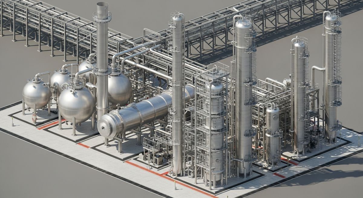
In my two decades of experience, I have seen projects succeed or fail based entirely on the initial plot plan. Fixing the location of various static equipment—such as fired heaters, reactors, and drums—is not merely about fitting components into a footprint; it is a rigorous exercise in balancing process flow, safety distances, and long-term maintenance accessibility.
When we define the location of static equipment, we are essentially setting the “DNA” of the plant. A poorly placed heat exchanger can turn a routine maintenance task into a multi-day shutdown, while an improperly oriented fired heater can create hazardous zones that restrict all other activities in the vicinity. This guide breaks down the technical requirements for these critical assets.
Key Takeaways for Layout Engineers:
- Prioritize bundle pull clearances for all shell-and-tube heat exchangers.
- Maintain strict fire-zone separation for fired heaters per API 560.
- Ensure reactor platforms allow for catalyst loading and unloading logistics.
- Integrate safety egress paths early in the plot plan development.
Technical Deep-Dive: Static Equipment Location Strategies
Static Equipment Location: The systematic application of spatial constraints and safety standards to optimize the arrangement of process equipment for operational efficiency and risk mitigation.
When determining the location of static equipment, we must first address the hierarchy of process flow. Fired heaters, as the primary heat source, typically dictate the “hot” end of the unit. According to API 560, these units require significant clearance from other process equipment to prevent fire propagation. I always recommend a minimum of 15 meters from any vessel containing flammable liquids, though site-specific risk assessments often push this to 20 meters or more.
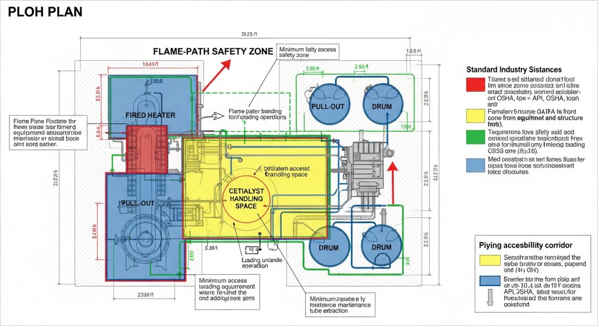
Reactors present a different challenge. Because they often require heavy lifting equipment for catalyst replacement, their location must be adjacent to primary access roads. The structural support for a reactor is significant; therefore, we must verify soil bearing capacity early. If the reactor is tall, wind load calculations according to ASCE 7 become the governing factor for foundation design and spacing from adjacent structures.
Field Warning: The Bundle Pull Trap
Never finalize the location of a horizontal heat exchanger without verifying the bundle pull path. I have seen designs where the exchanger was perfectly placed for piping, but the bundle pull path was blocked by a structural column or a pipe rack support. Always ensure the clear space equals the tube length plus at least 1.5 meters for the pulling machine.
For drums and pressure vessels, the primary constraint is the elevation required for NPSH (Net Positive Suction Head) of downstream pumps. If a drum is located too far from its associated pump, the frictional pressure drop in the suction line will exceed the available head, leading to cavitation. We calculate the required elevation (Z) using the formula: Z = (NPSH_required + H_f – P_v) / rho * g, where H_f represents frictional losses and P_v is the vapor pressure of the fluid.
Finally, consider the maintenance access for valves and instrumentation. Every static equipment item must have a clear path for mobile equipment like cranes and forklifts. If the equipment is located in a congested area, we must account for the swing radius of the crane. I suggest using a 3D model to perform a “crane reach analysis” during the 30% design review phase to avoid costly field modifications later.
Strategic Equipment Placement: The trade-off between compact plant footprint and long-term operational maintainability and safety.
Advantages
- Reduced piping runs minimize pressure drop and capital expenditure.
- Centralized maintenance zones improve turnaround efficiency.
- Optimized spacing enhances natural ventilation, reducing gas accumulation risks.
- Improved structural grouping simplifies foundation and drainage design.
Disadvantages
- High density increases the risk of domino-effect accidents during fires.
- Limited access for heavy mobile equipment during emergency repairs.
- Increased complexity in underground utility routing and drainage.
- Potential for vibration interference between closely spaced rotating and static equipment.
Industrial Equipment Integration: The practical deployment of static equipment in diverse process environments to meet specific safety and throughput requirements.
Refinery Hydroprocessing Units
In hydroprocessing, the reactor location is dictated by the high-pressure hydrogen service and the need for rapid catalyst change-out. We place these reactors in a dedicated “high-bay” area to allow for vertical crane access, ensuring that the surrounding piping is routed overhead to keep the ground level clear for heavy-duty transport vehicles.
Natural Gas Liquefaction Plants
Cryogenic heat exchangers in LNG plants require extreme precision in location due to thermal expansion and contraction cycles. We utilize flexible piping loops and ensure that the equipment is mounted on low-friction sliding supports, with spacing calculated to accommodate the significant movement of the exchanger shells during startup and shutdown sequences.
Petrochemical Distillation Columns
For large-scale distillation columns, the location is determined by the reboiler and condenser integration. By placing the reboiler directly beneath the column, we minimize the vapor return line length, which significantly reduces the pressure drop and improves the overall separation efficiency of the column, directly impacting the product purity and energy consumption.
In my two decades of plant layout design, I have observed that the most common failures in site safety stem from inadequate spacing between high-energy static equipment. When positioning fired heaters, reactors, and pressure vessels, we must adhere to strict minimum separation distances to mitigate the risk of fire propagation and to ensure that maintenance crews have sufficient room for heavy lifting equipment. These distances are not merely suggestions; they are codified requirements that dictate the footprint of the entire process unit.
The following table summarizes the typical minimum clear distances required between various classes of static equipment. These values are derived from industry-standard practices such as API RP 752 and NFPA 30. Please note that these figures represent the absolute minimums; site-specific risk assessments, such as Quantitative Risk Analysis (QRA), often mandate significantly larger buffers depending on the process fluid’s volatility and the operating pressure of the vessel.
| Equipment Pair | Min. Distance (m) | Primary Driver |
|---|---|---|
| Fired Heater to Reactor | 15.0 | Radiant heat/Fire hazard |
| Reactor to Exchanger Bank | 6.0 | Maintenance access/Tube pull |
| Drum to Drum (Process) | 3.0 | Operational clearance |
| Fired Heater to Control Room | 30.0 | Blast/Fire protection |
Always verify these distances against your local jurisdictional codes and the specific insurance requirements of the project. If you are working in a brownfield environment, these distances often become the primary constraint for piping routing and structural steel placement.
Effective plant layout requires a deep understanding of how different equipment entities interact within the process flow. This matrix maps the critical technical parameters that influence the physical location of static equipment. By categorizing equipment based on their thermal output, maintenance frequency, and pressure containment requirements, we can establish a logical hierarchy for site zoning.
The matrix below serves as a quick-reference guide for engineers to identify the governing standards and physical constraints for each equipment type. When designing the plot plan, I recommend using this matrix to cross-reference your equipment list against the required safety zones and utility access points. This ensures that high-maintenance items are not buried in the center of the unit, which would otherwise lead to excessive downtime during turnarounds.
| Equipment | Key Constraint | Standard |
|---|---|---|
| Fired Heater | Combustion Air/Stack Height | API 560 |
| Reactor | Catalyst Loading/Unloading | ASME VIII |
| Exchanger | Tube Bundle Pull Space | TEMA |
| Pressure Drum | Relief System Routing | ASME B31.3 |
By maintaining this technical mapping, you ensure that your design remains compliant with international safety standards while optimizing the physical footprint of the facility.
Before finalizing the plot plan for any static equipment, I perform a rigorous site verification. This process is designed to catch spatial conflicts that could lead to costly field rework or, worse, operational hazards. The following checklist is a synthesis of my experience in commissioning and design review, ensuring that every piece of equipment is positioned for both safety and long-term maintainability.
- ✓ Verify that the fired heater stack is positioned downwind of the main process area to prevent gas ingestion.
- ✓ Confirm that all heat exchangers have a clear, unobstructed path for tube bundle extraction using a mobile crane.
- ✓ Ensure that reactor manways are accessible via permanent platforms and that the catalyst handling area is clear of overhead pipe racks.
- ✓ Check that all pressure relief valves (PRVs) on drums have a direct, short path to the flare header to minimize backpressure.
- ✓ Validate that the foundation design accounts for the soil bearing capacity and potential vibration from nearby rotating equipment.
- ✓ Confirm that all equipment is located outside of the blast radius of high-pressure vessels as defined by the site safety study.
Each item on this list must be signed off by both the lead piping engineer and the process safety engineer. In my experience, skipping the verification of the tube bundle pull space is the most common cause of project delays during the first turnaround. Always treat the “clear space” as a non-negotiable design parameter, regardless of how tight the plot plan may be.
The Problem: Inadequate Maintenance Access for Reactor Catalyst Loading
- The reactor was positioned too close to the main pipe rack, blocking the primary crane access path.
- Catalyst loading nozzles were oriented toward a congested area, preventing the use of standard loading equipment.
- The lack of a permanent platform meant that temporary scaffolding was required for every inspection, adding weeks to the turnaround schedule.
- The proximity to the fired heater created a heat stress hazard for personnel working on the reactor top.
The Outcome: Optimized Layout and Reduced Turnaround Time
- Relocated the reactor 4 meters away from the pipe rack, allowing for direct crane access to the manway.
- Re-oriented the loading nozzles to face the open maintenance aisle, reducing loading time by 40 percent.
- Installed a permanent, integrated platform system that eliminated the need for temporary scaffolding.
- Implemented a heat shield between the heater and the reactor, improving the working environment for maintenance crews.
This case study highlights the importance of early-stage layout reviews. By involving the maintenance team in the initial design phase, we were able to identify these constraints before the concrete was poured. My recommendation is to always conduct a 3D model review with the maintenance and operations staff to simulate the actual removal and replacement of equipment components.
What is the primary factor for fired heater placement?
- Ensure the stack height is sufficient to disperse flue gases away from elevated platforms.
- Maintain minimum separation distances from other process units to prevent fire propagation.
- Consider the prevailing wind direction during the initial plot plan development.
How do I calculate tube bundle pull space?
- Add at least 1.5 meters of extra clearance beyond the bundle length for maneuvering.
- Ensure the path is free of structural steel, piping, or cable trays.
- Verify that the ground surface is capable of supporting the weight of the bundle puller.
Are there specific rules for drum orientation?
- Ensure that relief valves are located at the highest point of the vessel.
- Orient the vessel to minimize the length of the piping run to the flare header.
- Provide adequate clearance for the removal of internal components like demister pads.
How does reactor height affect site layout?
- Consider the impact of the reactor height on the site’s skyline and potential aviation restrictions.
- Ensure that the support structure allows for thermal expansion of the vessel.
- Verify that the platform levels align with the required maintenance access points.
What is the role of QRA in equipment location?
- Use QRA to justify deviations from standard spacing requirements.
- Identify high-risk equipment that should be isolated from the main control room.
- Validate the effectiveness of blast walls and fireproofing measures.
How to manage piping stress in static equipment?
- Use expansion loops or bellows to absorb thermal movement.
- Design support systems that allow for controlled movement of the piping.
- Perform stress analysis for all critical connections to prevent nozzle failure.
📚 Recommended Resources: Static Equipment Location
Read these Guides

Complete Course on
Piping Engineering
Check Now
Key Features
- 125+ Hours Content
- 500+ Recorded Lectures
- 20+ Years Exp.
- Lifetime Access
Coverage
- Codes & Standards
- Layouts & Design
- Material Eng.
- Stress Analysis
