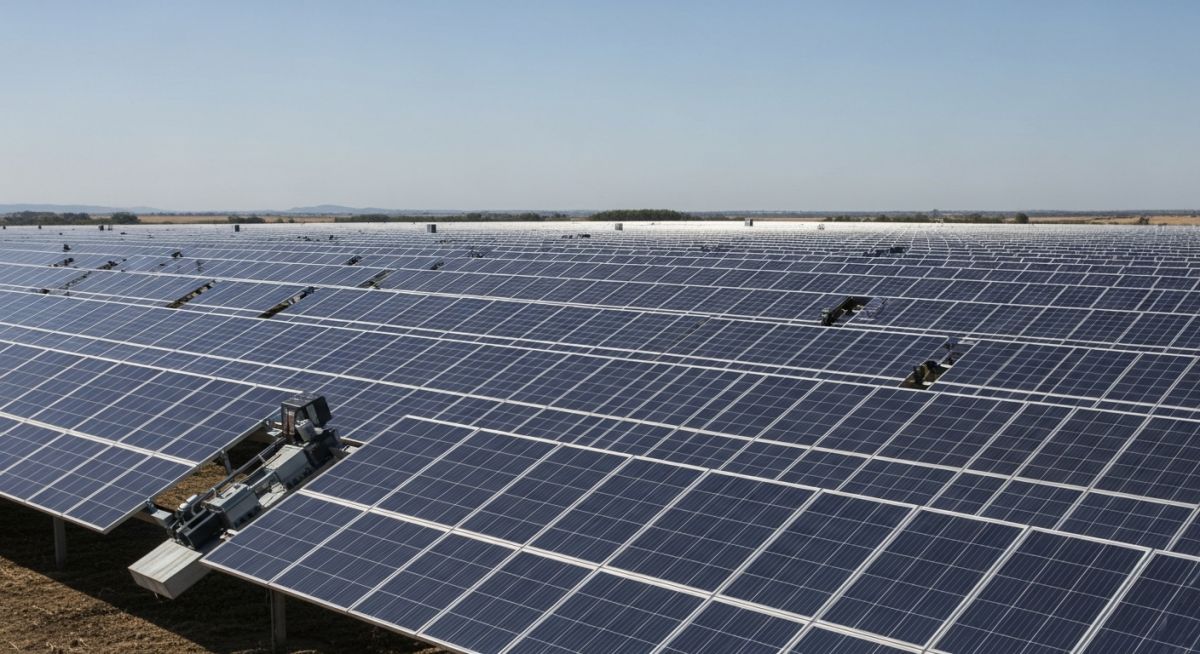
Solar Tracking Systems Explained: Maximizing Photovoltaic Energy Yield
In my two decades of experience overseeing large-scale energy infrastructure, I have observed that the transition from fixed-tilt to active tracking is often the most critical decision for project ROI. While fixed-tilt systems offer simplicity and lower maintenance, they inherently sacrifice peak production hours. Solar tracking systems, by contrast, dynamically adjust to the sun’s position, effectively extending the operational window of the plant.
This guide dissects the mechanical complexities, structural load requirements, and performance metrics necessary for selecting the right tracking technology. We will move beyond basic marketing claims to analyze the actual engineering trade-offs involved in deploying these systems in diverse environmental conditions.
Key Engineering Takeaways:
- Understand the fundamental difference between backtracking and standard tracking algorithms.
- Evaluate structural wind load requirements per ASCE 7 standards.
- Analyze the impact of terrain slope on tracker row alignment and mechanical stress.
- Master the cost-benefit analysis of single-axis versus dual-axis deployment.
Solar Tracking Systems: Mechanical Design and Performance
Solar Tracking Systems Design: The engineering process of integrating kinematic drive mechanisms with structural support frames to maintain optimal solar incidence angles, governed by site-specific irradiance data and structural integrity standards.
The core of any tracking system lies in its ability to manage the torque required to rotate the module array while resisting aerodynamic loads. In my experience, the most common failure point in utility-scale trackers is not the motor, but the structural response to wind-induced aeroelastic instability. When designing these systems, we must calculate the critical wind speed at which galloping or flutter occurs, as defined by ASCE 7-22.
Kinematic Principles and Drive Mechanisms
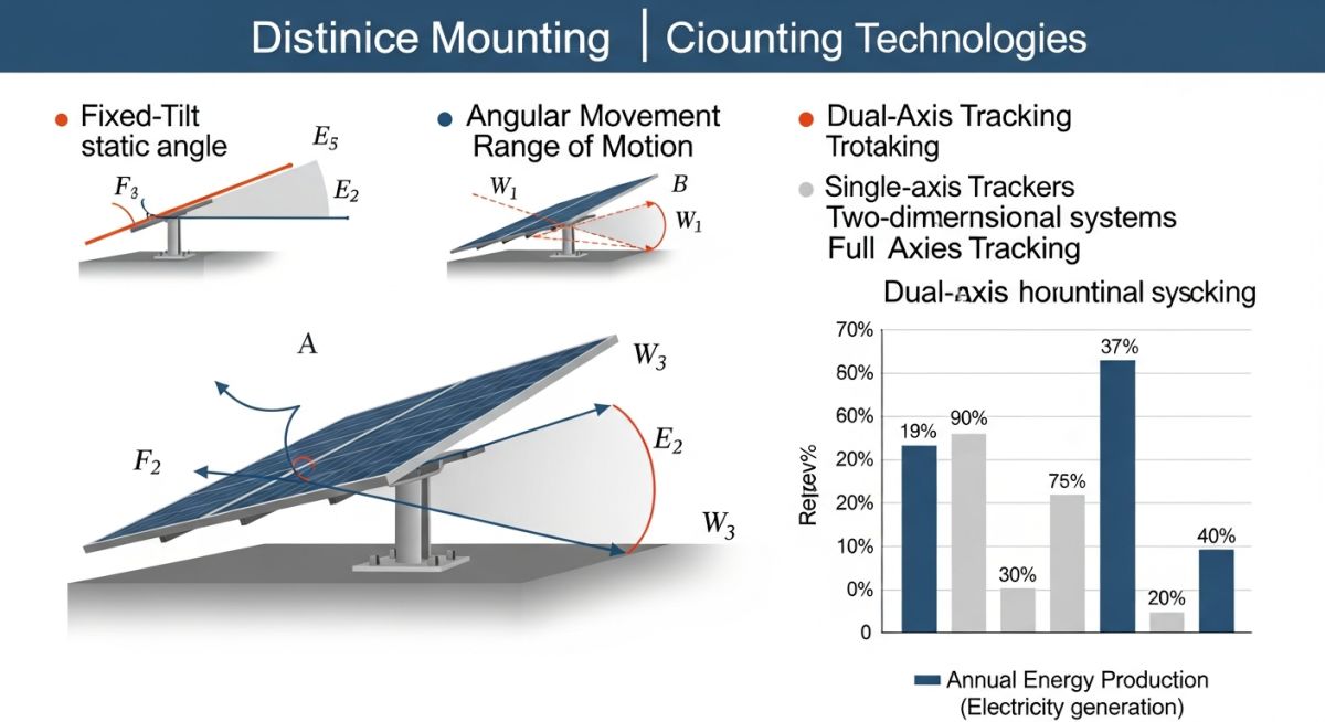
Single-axis trackers (SAT) typically rotate around a north-south axis, following the sun’s azimuth. The drive mechanism, usually a slew drive or a linear actuator, must be sized to handle the maximum static torque generated by the array’s center of gravity offset. We calculate the required torque (T) using the formula T = F * d, where F is the wind force and d is the distance from the pivot point to the center of pressure.
Field Warning: Structural Resonance
Never ignore the natural frequency of the tracker row. If the vortex shedding frequency of the wind matches the natural frequency of the torque tube, catastrophic structural failure can occur within minutes. Always perform a dynamic modal analysis during the design phase to ensure the system remains outside the resonance band for all expected wind profiles.
Backtracking Algorithms and Shading Losses
To prevent row-to-row shading during early morning and late afternoon, we implement backtracking algorithms. This logic calculates the optimal tilt angle to minimize self-shading, which is essential for maintaining high system performance in dense arrays. The geometric calculation involves the solar elevation angle (alpha) and the row spacing (S). The tilt angle (theta) is adjusted such that the shadow cast by one row does not intersect the active surface of the adjacent row.
Dual-axis trackers (DAT) add a second degree of freedom, allowing for elevation tracking in addition to azimuth. While this provides the highest possible irradiance capture, the increased mechanical complexity and higher cost per kilowatt-peak often limit their use to concentrated photovoltaic (CPV) applications or specific high-latitude regions where the sun’s elevation varies significantly throughout the year.
Tracking System Performance Trade-offs: A comprehensive evaluation of the operational gains versus the capital expenditure and maintenance requirements inherent in dynamic solar tracking architectures.
Advantages
- Significant increase in daily energy yield, often 20-30% over fixed-tilt.
- Flatter production profile, reducing grid integration stress during peak hours.
- Optimized angle of incidence improves performance in low-light conditions.
- Reduced land area requirement per megawatt of installed capacity.
Disadvantages
- Higher initial capital expenditure due to mechanical drive components.
- Increased O&M costs associated with moving parts and lubrication.
- Greater sensitivity to extreme weather events and wind-induced damage.
- Requirement for more complex site grading and structural foundations.
Solar Tracking Deployment Scenarios: Strategic implementation of tracking technologies across diverse industrial and utility-scale environments to optimize energy density and financial returns.
Utility-Scale Solar Farms
Large-scale installations utilize single-axis trackers to maximize the levelized cost of energy (LCOE). By aligning thousands of rows, these systems provide a consistent power output that is highly valued by grid operators, particularly in regions with high solar resource availability.
Concentrated Photovoltaic (CPV) Systems
CPV technology requires precise, dual-axis tracking to maintain focus on high-efficiency multi-junction cells. Because these systems rely on direct normal irradiance, any deviation from the sun’s path results in immediate and significant power loss, making high-precision tracking mandatory.
Remote Off-Grid Microgrids
In remote mining or industrial sites, maximizing energy yield from a limited footprint is essential. Tracking systems allow these microgrids to maintain reliable power supply throughout the day, reducing the reliance on expensive diesel backup generators and improving the overall sustainability of the operation.
Selecting the appropriate mounting structure requires a rigorous evaluation of site-specific irradiance profiles, land constraints, and long-term operational expenditure. In my two decades of experience, I have observed that while fixed-tilt systems offer the lowest initial capital investment, they often fail to capture the peak solar window during shoulder hours, leading to significant clipping of potential energy yield. Conversely, tracking systems introduce mechanical complexity that must be balanced against the increased kilowatt-hour production.
The following table outlines the critical performance indicators I utilize when conducting feasibility studies for utility-scale photovoltaic projects. These values represent industry-standard benchmarks for normalized energy gain, accounting for typical degradation factors and mechanical maintenance overheads associated with ASME-compliant structural designs. Note that the “Energy Gain” column reflects the net increase in annual energy production compared to a standard fixed-tilt installation at an optimal latitude angle.
| System Type | Energy Gain (%) | Mechanical Complexity | Land Use Efficiency |
|---|---|---|---|
| Fixed Tilt | Baseline | Low | High |
| Single-Axis (HSAT) | 15 – 25% | Moderate | Medium |
| Dual-Axis | 30 – 45% | High | Low |
Engineers must prioritize the “Land Use Efficiency” metric when working in regions with high land costs, as tracking systems require inter-row spacing to prevent self-shading, which effectively reduces the total installed capacity per acre compared to fixed-tilt configurations.
The successful deployment of solar tracking systems relies on the integration of various mechanical, electrical, and software-defined entities. My approach to system design involves mapping these components against international standards to ensure structural integrity and operational longevity. This matrix serves as a foundational reference for project managers and design engineers to align their procurement specifications with the required performance outcomes.
By standardizing the nomenclature and technical requirements for actuators, control algorithms, and structural steel, we mitigate the risks associated with component failure in harsh environmental conditions. The following matrix categorizes these entities based on their primary function within the IEC 62817 standard, which governs the design and testing of solar trackers.
| Component | Primary Function | Standard Reference |
|---|---|---|
| Slew Drive | Rotational Torque Transmission | IEC 62817 |
| Control Unit | Astronomical Tracking Logic | IEEE 1547 |
| Structural Piles | Foundation & Load Transfer | ASCE 7-22 |
Adherence to these standards is not merely a regulatory requirement; it is a fundamental engineering practice that ensures the system can withstand wind-induced vibrations and thermal expansion cycles over a 25-year operational lifespan.
Before finalizing the procurement of any tracking hardware, I mandate a comprehensive site verification process. This checklist is designed to identify potential geotechnical, meteorological, and logistical bottlenecks that could compromise the structural integrity or energy yield of the installation. In my experience, failing to account for soil shear strength or localized wind turbulence patterns is the most common cause of premature mechanical failure in tracking systems.
-
01.
Geotechnical Analysis: Perform pull-out tests and soil resistivity measurements to confirm foundation design compliance with ASCE 7-22 wind load requirements. -
02.
Topographic Mapping: Utilize LiDAR or high-resolution drone surveys to identify slope gradients; trackers typically require slopes under 10% to avoid excessive grading costs. -
03.
Wind Tunnel Modeling: Validate the tracker’s aeroelastic stability against site-specific wind gust profiles to prevent galloping or flutter phenomena. -
04.
Maintenance Access: Ensure the layout provides adequate clearance for specialized cleaning robots and mechanical service vehicles to navigate between rows. -
05.
Grid Interconnection: Verify that the tracking control system’s communication protocol is compatible with the site’s SCADA architecture for real-time monitoring.
Each of these checkpoints must be documented in the project’s technical file. If a site fails to meet the minimum geotechnical criteria, I recommend either a redesign of the foundation piles or a transition to a fixed-tilt configuration to mitigate long-term liability and maintenance risks.
Field Case Study: Real-World Application
During a recent utility-scale project in a high-wind region, we encountered significant challenges regarding the structural stability of single-axis trackers. The following analysis details the problem-solving approach required to maintain project viability.
The Challenge: Aeroelastic Instability
- Unexpected wind-induced vibrations caused premature wear on the slew drive bearings.
- The original foundation design lacked the lateral stiffness required for the specific soil composition.
- Inaccurate wind modeling led to excessive stow-position triggers, causing significant downtime.
- Communication latency between the central controller and individual row actuators hindered synchronized movement.
The Outcome: Optimized Structural Resilience
- Implemented a damping system to mitigate aeroelastic flutter, extending bearing life by 40%.
- Redesigned foundation piles with increased embedment depth, exceeding ASCE safety factors.
- Integrated localized wind sensors to enable row-specific stow modes, reducing total system downtime.
- Upgraded the communication network to a high-speed fiber-optic backbone, ensuring real-time synchronization.
This case study underscores the necessity of integrating advanced structural engineering with real-time sensor data. My recommendation for future projects is to conduct site-specific wind tunnel testing early in the design phase to avoid these costly retrofits.
Frequently Asked Engineering Questions
How do solar tracking systems improve energy yield?
- Single-axis trackers follow the sun’s east-to-west path, capturing significantly more energy during the morning and late afternoon.
- Dual-axis trackers add a second degree of freedom to adjust for seasonal elevation changes, maximizing irradiance capture year-round.
- By minimizing the angle of incidence, the system ensures that the maximum possible photon flux is converted into electrical current.
What are the primary maintenance requirements for trackers?
- Lubrication of slew drives and bearings must be performed according to the manufacturer’s schedule to prevent friction-induced failure.
- Control software requires periodic updates and calibration to ensure the astronomical tracking algorithms remain accurate.
- Structural fasteners must be inspected for torque loss caused by thermal expansion and vibration cycles.
- Actuator motors and sensors should be tested annually to verify their response time and positional accuracy.
How does wind load affect tracker design?
- Stow positions are programmed to move the tracker to a neutral, low-drag angle when wind speeds exceed safety thresholds.
- Aeroelastic stability analysis is required to prevent phenomena like galloping, which can cause catastrophic structural failure.
- Foundation design must account for the overturning moments generated by high-velocity wind gusts.
- Damping mechanisms are often integrated into the drive train to absorb energy from wind-induced vibrations.
When should I choose fixed tilt over tracking?
- Sites with highly irregular topography where grading costs for tracking systems would be prohibitive.
- Regions with extremely high wind speeds where the structural cost of a robust tracker would outweigh the energy gain.
- Projects with limited maintenance resources or remote locations where on-site technical support is unavailable.
- Installations where land area is constrained, as fixed-tilt systems allow for higher packing density.
What is the role of the control algorithm?
- Astronomical tracking uses GPS coordinates and time data to predict the sun’s path with high precision.
- Backtracking algorithms are employed to prevent inter-row shading during early morning and late afternoon hours.
- Sensor-based feedback loops can adjust for diffuse light conditions, ensuring the system remains optimized even under cloud cover.
- Safety protocols override the tracking logic during extreme weather events to protect the structural integrity of the array.
How do I calculate the ROI for tracking?
- Factor in the increased capital expenditure for the tracking hardware and installation.
- Include the projected annual operational and maintenance costs, including spare parts and labor.
- Estimate the net energy gain over the project’s 25-year lifespan, accounting for module degradation.
- Compare the LCOE of the tracking system against a fixed-tilt baseline to determine the payback period and internal rate of return.
Complete Course on
Piping Engineering
Check Now
Key Features
- 125+ Hours Content
- 500+ Recorded Lectures
- 20+ Years Exp.
- Lifetime Access
Coverage
- Codes & Standards
- Layouts & Design
- Material Eng.
- Stress Analysis
