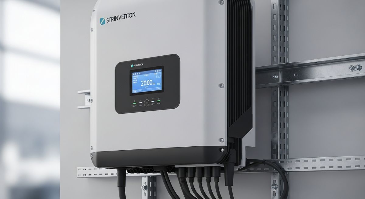
Solar Inverters Explained: Engineering Principles and System Integration
In my two decades of managing complex energy infrastructure, I have observed that the inverter is the true “brain” of any photovoltaic system. While panels capture sunlight, the inverter dictates the efficiency, safety, and grid-compatibility of the entire installation. Understanding how these units handle variable DC inputs and translate them into stable, synchronized AC power is fundamental for any engineer tasked with renewable energy deployment.
This guide dissects the technical architecture of modern inverters, moving beyond marketing brochures to address the actual electrical stresses, thermal management, and control logic that define long-term project reliability.
Key Engineering Takeaways:
- Mastering MPPT logic for varying irradiance profiles.
- Evaluating Total Harmonic Distortion (THD) for grid compliance.
- Thermal derating factors in high-ambient temperature environments.
- Selecting between string, central, and hybrid topologies based on site-specific constraints.
Solar Inverters Explained: Core Technical Architecture
Solar Inverter Design: These power conversion systems integrate complex semiconductor switching, filtering, and control loops to maintain stable power delivery under fluctuating environmental conditions as defined by IEC 62109 safety standards.
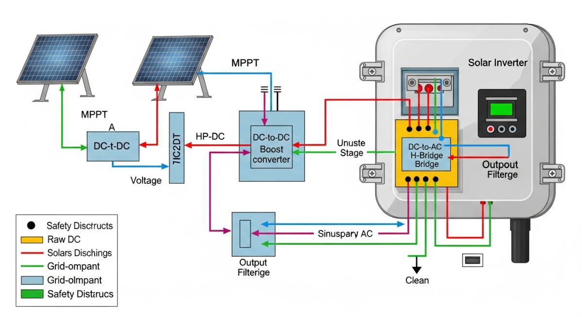
At the heart of the inverter lies the Pulse Width Modulation (PWM) switching bridge, typically composed of Insulated Gate Bipolar Transistors (IGBTs). These transistors switch at high frequencies—often between 5 kHz and 20 kHz—to synthesize a sinusoidal AC waveform from the raw DC input. The efficiency of this process is governed by the switching losses and conduction losses within the semiconductors.
Maximum Power Point Tracking (MPPT) Logic
The MPPT algorithm is the primary control mechanism for maximizing energy harvest. By continuously adjusting the electrical load on the PV array, the inverter forces the system to operate at the “knee” of the I-V curve where power output is maximized. In my experience, the precision of this tracking—often exceeding 99.5% efficiency—is what separates industrial-grade hardware from residential-grade components.
Field Warning: Thermal Derating
Engineers must account for thermal derating when sizing inverters for desert or high-heat industrial sites. As internal component temperatures rise, the inverter control logic will automatically reduce the power output to protect the IGBTs. Always verify the manufacturer’s derating curve against the peak ambient temperature of your specific site location to avoid unexpected capacity loss.
Grid Synchronization and Protection
Beyond conversion, the inverter must act as a grid-interactive device. It monitors grid voltage and frequency, performing anti-islanding protection to disconnect the system if the grid fails. This is critical for utility safety. The output filter, usually an LCL configuration, is essential to suppress high-frequency switching noise, ensuring that the Total Harmonic Distortion (THD) remains below the 5% threshold required by most utility interconnection agreements.
Inverter System Trade-offs: Selecting the optimal topology requires balancing capital expenditure against long-term operational availability and system-wide energy yield performance metrics.
Technical Advantages
- High conversion efficiency exceeding 98.5% in modern units.
- Advanced MPPT algorithms minimize losses from partial shading.
- Integrated data logging for real-time performance monitoring.
- Modular design allows for rapid field replacement of sub-assemblies.
- Enhanced grid support features like reactive power control.
Technical Disadvantages
- High sensitivity to extreme ambient temperatures and humidity.
- Electrolytic capacitor degradation limits service life to 10-15 years.
- Complex firmware updates require specialized technical support.
- Potential for high-frequency noise interference with site communications.
- Significant cooling requirements for high-capacity central units.
Inverter Deployment Scenarios: Diverse industrial and utility-scale environments necessitate specific inverter configurations to ensure maximum reliability and grid-code compliance across varying load profiles.
Utility-Scale Solar Farms
Central inverters are the standard for large-scale utility projects due to their high power density and lower cost per watt. These units manage multi-megawatt arrays, requiring robust cooling systems and sophisticated grid-following control logic to maintain stability across the transmission interface.
Commercial Rooftop Installations
String inverters are preferred for commercial rooftops where shading from HVAC units or parapets is common. By utilizing multiple MPPT channels, these inverters isolate the impact of shading to specific strings, preventing the entire array’s performance from being dragged down by a single underperforming module.
Microgrid and Hybrid Systems
Hybrid inverters integrate battery storage management directly into the DC-coupled architecture, allowing for seamless transition between grid-tied and islanded modes. These are essential for industrial facilities requiring uninterruptible power supply (UPS) capabilities during grid instability or peak-shaving operations.
Selecting the correct inverter topology requires a rigorous evaluation of electrical performance metrics against site-specific environmental conditions. In my experience, engineers often overlook the correlation between ambient temperature derating and the total harmonic distortion (THD) limits defined by IEEE 519 standards. The following table provides a comparative baseline for standard inverter architectures, focusing on efficiency curves and operational voltage windows that dictate system-level reliability.
When reviewing these parameters, consider the impact of Maximum Power Point Tracking (MPPT) granularity on overall energy yield. High-frequency switching in modern power electronics allows for tighter control, but it also introduces challenges regarding electromagnetic interference (EMI) and thermal management within the enclosure. Always cross-reference these values with the manufacturer’s specific datasheet for the IEC 62109 safety compliance certification.
| Inverter Type | Efficiency Range | MPPT Channels | Primary Application |
|---|---|---|---|
| String Inverter | 97.5% – 98.8% | 2 to 6 | Commercial/Residential |
| Central Inverter | 98.5% – 99.2% | 1 (Centralized) | Utility-Scale PV |
| Hybrid Inverter | 96.0% – 97.5% | 2 to 4 | Energy Storage Systems |
The data above highlights the trade-off between centralized efficiency and distributed flexibility. While central inverters offer superior conversion efficiency for large-scale arrays, the lack of individual string-level MPPT can lead to significant energy losses in the presence of partial shading or module mismatch. Conversely, string inverters provide granular control, which is vital for complex roof geometries or sites with varying irradiance profiles.
To effectively manage the integration of solar inverters into a broader electrical grid, engineers must map specific hardware entities to their corresponding regulatory and physical constraints. This matrix serves as a technical reference for identifying the critical components that influence system-wide stability, including DC-to-AC conversion stages, grid-synchronization protocols, and protection mechanisms required by NFPA 70 (NEC).
Understanding these relationships is essential for troubleshooting communication failures or power quality issues. By aligning the physical hardware with the logical control parameters, you can ensure that the inverter remains within its safe operating area (SOA) throughout the lifecycle of the PV installation. This mapping also assists in the procurement process by standardizing the technical requirements across different vendor platforms.
| Entity | Function | Standard Reference |
|---|---|---|
| DC-DC Converter | Voltage Boosting/MPPT | IEEE 1547 |
| Inverter Bridge | DC to AC Inversion | IEC 62109 |
| Grid Interface | Synchronization/Protection | UL 1741 |
The matrix above provides a structured approach to system design. By focusing on these core entities, you can isolate performance bottlenecks and ensure that the inverter’s firmware and hardware configurations are optimized for the specific grid code requirements of the project location. Always verify that the selected equipment supports the necessary reactive power control features required by local utility interconnection agreements.
Successful commissioning of a solar inverter system requires a systematic verification process to ensure that all electrical, thermal, and communication parameters are within the design specifications. In my professional practice, I have found that a rigorous pre-energization checklist prevents the majority of field failures and warranty claims. This checklist focuses on the critical interface points between the PV array, the inverter, and the utility grid, ensuring compliance with NEC Article 690.
-
1.
Verify DC input voltage polarity and open-circuit voltage (Voc) against the inverter’s maximum input rating to prevent catastrophic damage. -
2.
Confirm that the AC output voltage and frequency settings match the local utility grid requirements as defined in IEEE 1547. -
3.
Inspect all cable terminations for proper torque settings to mitigate the risk of arc faults and thermal degradation over time. -
4.
Validate the grounding system continuity, ensuring that the equipment grounding conductor (EGC) is properly bonded to the inverter chassis. -
5.
Check the environmental clearance around the inverter to ensure adequate airflow for passive or active cooling systems. -
6.
Perform a communication link test to ensure the inverter is correctly reporting data to the monitoring platform for performance tracking.
Following this checklist ensures that the installation meets both safety and performance standards. Always document the results of these checks in the commissioning report, as this data is vital for long-term maintenance and troubleshooting. If any parameter falls outside the acceptable range, do not energize the system until the root cause is identified and rectified by a qualified technician.
Field Case Study: Real-World Application
Problem: Persistent Inverter Tripping in High-Temperature Environment
A 500kW commercial PV installation experienced frequent, intermittent shutdowns during peak summer months, leading to significant energy production losses.
- Inadequate thermal dissipation due to improper inverter mounting orientation.
- Voltage rise at the point of common coupling (PCC) exceeding the inverter’s high-voltage trip threshold.
- Accumulation of dust on heat sinks reducing the efficiency of the cooling fans.
- Inconsistent firmware versions across the string inverter fleet causing synchronization errors.
Outcome: Optimized Thermal Management and Grid Stability
The implementation of a comprehensive remediation plan restored system reliability and increased total uptime by 15% within the first quarter.
- Installed external shading structures to reduce direct solar gain on the inverter enclosures.
- Adjusted the inverter’s reactive power control settings to mitigate voltage rise at the PCC.
- Implemented a quarterly preventative maintenance schedule for cleaning heat sinks and verifying fan operation.
- Standardized firmware across all units to ensure uniform grid-following behavior and improved communication stability.
The recommendation for similar projects is to conduct a thorough thermal analysis during the design phase. By accounting for local climate extremes and grid impedance, you can select inverters with sufficient derating margins and robust control algorithms, preventing these common operational pitfalls before they occur.
Frequently Asked Engineering Questions
How does MPPT improve solar inverter efficiency?
- It continuously monitors the voltage and current output of the PV strings.
- The algorithm calculates the product of voltage and current to find the maximum power point.
- By adjusting the DC-DC converter duty cycle, it matches the array impedance to the inverter’s input requirements.
- This process maximizes energy harvest, especially during partial shading or non-ideal solar conditions.
What is the difference between string and central inverters?
- String inverters allow for multiple MPPT channels, providing better performance in shaded or complex environments.
- Central inverters aggregate the output of many strings into a single large conversion unit, reducing the number of components and simplifying maintenance.
- Central inverters are typically more cost-effective for large-scale utility projects where the array is uniform.
- String inverters offer higher system redundancy, as the failure of one unit does not disable the entire array.
Why is inverter derating a critical design factor?
- High ambient temperatures force the inverter to limit power to protect internal power electronics.
- High altitude operation reduces the cooling efficiency of air-cooled inverters, necessitating a derating factor.
- Grid voltage fluctuations can also trigger derating to maintain stability and prevent over-voltage trips.
- Engineers must account for these factors during the sizing phase to ensure the system meets its annual energy production targets.
How do hybrid inverters manage energy storage?
- They feature a bidirectional DC-DC converter to manage battery charging and discharging.
- The control logic prioritizes self-consumption, storing excess solar energy for use during peak demand or grid outages.
- They provide backup power capabilities, often with automatic transfer switches to isolate the home from the grid.
- Advanced energy management systems (EMS) within the inverter optimize battery health and cycle life.
What are the common causes of inverter communication failure?
- Poor signal strength in wireless (Wi-Fi) connections due to distance or physical obstructions.
- Corroded or loose Ethernet cable terminations in outdoor environments.
- IP address conflicts or firewall settings on the local network blocking the inverter’s traffic.
- Firmware mismatches between the inverter and the communication gateway or data logger.
How do grid codes influence inverter selection?
- Inverters must support “ride-through” capabilities, allowing them to remain connected during minor grid voltage or frequency disturbances.
- Reactive power control (Volt-VAR) is often required to help regulate local grid voltage levels.
- Anti-islanding protection is mandatory to prevent the inverter from energizing a de-energized grid section, protecting utility workers.
- Compliance with IEEE 1547 or local equivalents is a prerequisite for interconnection approval.
Complete Course on
Piping Engineering
Check Now
Key Features
- 125+ Hours Content
- 500+ Recorded Lectures
- 20+ Years Exp.
- Lifetime Access
Coverage
- Codes & Standards
- Layouts & Design
- Material Eng.
- Stress Analysis
