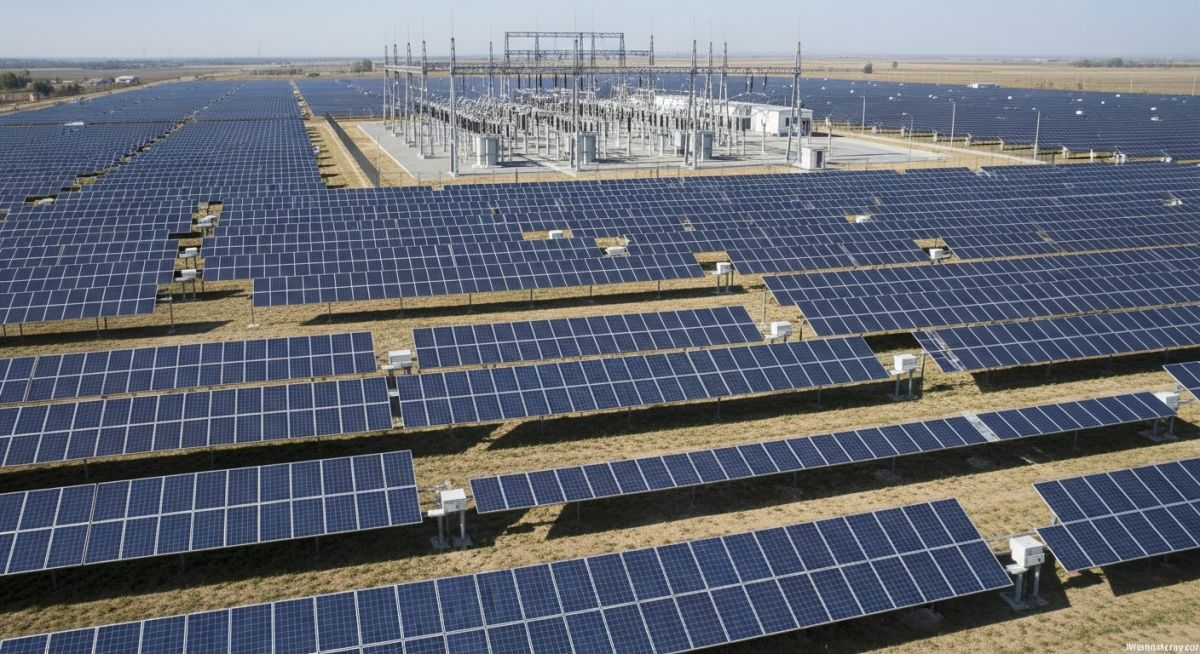
Solar Power Plant Design: A Comprehensive Engineering Development Guide
In my two decades of experience managing large-scale energy infrastructure, I have learned that successful solar power plant design is rarely about the panels themselves. It is about the rigorous orchestration of civil site preparation, electrical impedance matching, and long-term structural integrity under varying environmental loads.
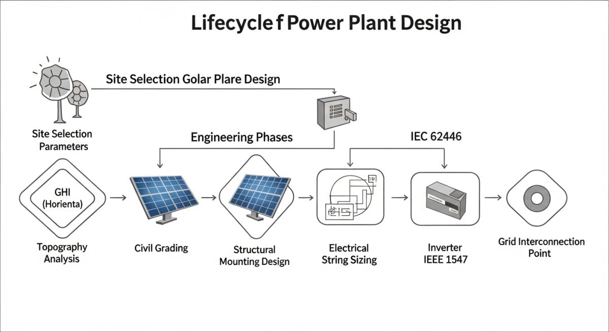
Whether you are navigating the complexities of NFPA 70 (National Electrical Code) or optimizing row-to-row spacing to minimize inter-row shading, the margin for error in utility-scale projects is razor-thin. This guide breaks down the development lifecycle into actionable engineering phases, ensuring your project meets both performance targets and regulatory compliance.
Key Engineering Takeaways:
- Optimizing Ground Coverage Ratio (GCR) for maximum energy yield.
- Mitigating voltage drop through strategic DC combiner box placement.
- Ensuring structural compliance with wind load standards like ASCE 7.
- Implementing robust grounding and lightning protection systems.
Technical Foundations of Solar Power Plant Design
Solar Power Plant Design: The multidisciplinary engineering process involving site geotechnical analysis, photovoltaic array configuration, and electrical power conversion systems designed to maximize Levelized Cost of Energy (LCOE) while maintaining grid stability.
Designing a utility-scale facility requires a deep dive into the physics of irradiance and the limitations of current-carrying conductors. We begin with the site selection, where geotechnical reports dictate the foundation type—typically driven piles or ground screws. I always emphasize that the soil’s corrosive potential must be tested against ASTM standards to prevent premature structural failure.
Calculating Array Performance and Shading
The primary design constraint is the inter-row spacing, which is a function of the latitude and the tilt angle of the modules. To calculate the minimum spacing (D), we use the formula D = L * sin(beta) / tan(alpha), where L is the length of the module, beta is the tilt angle, and alpha is the solar elevation angle at the winter solstice.
Engineering Warning: Thermal Expansion
In large-scale tracker systems, thermal expansion of the torque tube can lead to mechanical binding. Always incorporate expansion joints and ensure the structural design accounts for the coefficient of thermal expansion of the steel grade used, typically ASTM A500.
Electrical Distribution and Impedance
Once the mechanical layout is fixed, the electrical design focuses on minimizing DC losses. I recommend keeping the DC cable runs from the modules to the combiner boxes under 100 meters to maintain voltage drop below 2%. The selection of conductors must comply with IEC 62852 for connectors and NEC Article 690 for system grounding.
The inverter selection is the next critical step. Central inverters are often preferred for utility-scale projects due to their higher efficiency and ease of maintenance compared to string inverters. However, they require a more complex medium-voltage (MV) collection system. Ensure the transformer sizing accounts for the inverter’s maximum continuous output plus a 10% safety margin for ambient temperature derating.
Solar Engineering Trade-offs: The critical evaluation of system architecture choices, balancing capital expenditure against long-term operational reliability and energy yield performance.
Advantages
- Scalability: Modular design allows for incremental capacity expansion.
- Low O&M: Absence of moving parts in fixed-tilt systems reduces maintenance.
- Predictability: Solar irradiance data allows for highly accurate yield modeling.
- Sustainability: Minimal environmental footprint during the operational phase.
Disadvantages
- Intermittency: Requires energy storage or grid balancing for baseload reliability.
- Land Intensity: Large utility-scale projects require significant acreage.
- Degradation: PV module efficiency drops over time, typically 0.5% annually.
- Grid Congestion: Remote locations often require expensive transmission line upgrades.
Utility-Scale Deployment: The application of solar power plant design principles across diverse industrial and regional sectors to achieve carbon neutrality and energy independence.
Industrial Feedstock Decarbonization
Large-scale manufacturing facilities utilize dedicated solar arrays to offset high-energy consumption processes. By integrating behind-the-meter generation, these plants reduce reliance on grid-supplied fossil fuels and stabilize long-term energy costs through Power Purchase Agreements (PPAs).
Remote Mining Site Electrification
Mining operations in isolated regions often rely on expensive diesel generators. Implementing a hybrid solar-plus-storage system significantly reduces fuel logistics costs and carbon emissions while providing a reliable, high-availability power source for heavy machinery.
Agricultural Agrivoltaics
This application combines solar energy production with crop cultivation, utilizing elevated mounting structures to provide shade for crops while generating electricity. This dual-use approach optimizes land productivity and reduces water evaporation in arid farming regions.
In my two decades of experience, I have found that the success of a utility-scale project hinges on the precise alignment of electrical and mechanical parameters. The table below outlines the critical design thresholds I utilize during the preliminary engineering phase to ensure compliance with IEEE and IEC standards. These values serve as the baseline for inverter sizing, string configuration, and transformer selection.
Engineers must note that these parameters are subject to site-specific derating factors, including ambient temperature coefficients and local irradiance profiles. Always verify your specific module datasheet against the NREL System Advisor Model to confirm that your chosen configuration remains within the safe operating area of the power conversion equipment.
| Parameter | Typical Range | Standard Reference |
|---|---|---|
| DC/AC Ratio | 1.2 to 1.4 | IEC 62548 |
| String Voltage (Max) | 1000V – 1500V | IEC 61730 |
| Inverter Efficiency | 98.0% – 99.2% | IEEE 1547 |
| Grounding Resistance | Less than 5 Ohms | IEEE 81 |
Effective project management requires a clear understanding of the interconnected entities that define a modern solar facility. This matrix maps the primary structural and electrical components to their respective regulatory frameworks and performance metrics. By maintaining this traceability, we ensure that every component—from the mounting structure to the SCADA interface—meets the rigorous demands of utility-scale operations.
I recommend using this matrix during the procurement and quality assurance phases to verify that all vendor documentation aligns with the project’s technical specifications. Discrepancies at this stage often lead to costly commissioning delays or long-term reliability issues that are difficult to rectify once the plant is energized.
Solar Power Plant Design: Comprehensive site verification is the bedrock of a bankable project. Before finalizing the layout, I mandate a rigorous site assessment to mitigate geotechnical risks and ensure optimal solar resource utilization. This checklist serves as your primary tool for field validation and compliance documentation.
- Geotechnical Survey: Confirm soil bearing capacity and corrosion potential per ASTM D2487 standards.
- Topographic Mapping: Verify site slope gradients to ensure tracker compatibility and minimize earthworks.
- Shading Analysis: Utilize LiDAR or drone-based surveys to identify permanent obstructions within the horizon.
- Grid Interconnection Point: Validate the physical distance and capacity of the nearest substation or transmission line.
- Environmental Compliance: Ensure site selection adheres to local wildlife protection and land-use zoning regulations.
- Access Infrastructure: Confirm road capacity for heavy equipment delivery during the construction phase.
Each item must be signed off by the lead site engineer. If any parameter falls outside the design envelope, you must re-evaluate the layout or implement mitigation strategies such as pile foundation adjustments or additional drainage systems. Never proceed to the procurement phase until these site-specific variables are fully reconciled with your BIM model.
Problem: Unexpected Soil Instability in Utility-Scale Project
During the construction of a 100MW facility, we encountered significant soil instability that threatened the structural integrity of the tracker foundations.
- Inaccurate initial geotechnical report failing to identify high-plasticity clay layers.
- Excessive pile pull-out force observed during initial load testing.
- Incompatibility between standard pile depth and site-specific soil saturation levels.
- Risk of long-term foundation settlement affecting tracker alignment and energy yield.
Outcome: Successful Foundation Redesign and Mitigation
We successfully stabilized the site by implementing a revised foundation strategy that ensured long-term operational reliability.
- Redesigned pile foundations using deeper embedment and helical anchors to bypass unstable layers.
- Implemented a site-wide drainage improvement plan to manage water runoff and soil moisture.
- Achieved 100% compliance with structural safety standards after re-testing.
- Minimized project schedule impact through rapid procurement of specialized foundation equipment.
My recommendation for future projects is to conduct localized geotechnical testing at every 500-meter interval across the site. Relying on regional data is insufficient for large-scale solar developments where soil heterogeneity can lead to catastrophic foundation failure.
How do I determine the optimal DC/AC ratio for a project?
The DC/AC ratio, or inverter loading ratio, is a critical design decision that balances capital expenditure against energy clipping losses. I typically evaluate this by analyzing the local irradiance profile and the inverter’s maximum power point tracking range.
- Higher ratios (1.3+) are beneficial in regions with lower average irradiance to maximize inverter utilization during shoulder hours.
- Consider the inverter’s thermal derating curve, as high DC input can lead to increased operating temperatures and potential premature component failure.
- Always simulate the clipping losses using software like PVSyst to ensure the increased energy production outweighs the cost of additional modules and mounting hardware.
What are the primary considerations for 1500V system design?
Transitioning to 1500V systems significantly reduces balance-of-system costs by allowing for longer string lengths and fewer combiner boxes. However, this shift introduces specific engineering challenges that must be addressed during the design phase.
- Ensure all cabling, connectors, and switchgear are rated for 1500V DC operation per IEC 62548.
- Pay close attention to creepage and clearance distances in electrical enclosures to prevent arc faults.
- Implement advanced insulation monitoring devices to detect ground faults early, as the higher voltage increases the risk of insulation degradation over time.
How does shading impact the performance of tracker systems?
Shading, particularly back-tracking, is a major factor in utility-scale solar power plant design. If not properly managed, row-to-row shading can significantly reduce the energy yield of the entire array.
- Utilize sophisticated back-tracking algorithms that adjust the tilt angle of the trackers to minimize self-shading during early morning and late afternoon.
- Perform a detailed 3D shading analysis to account for site topography, as uneven terrain can exacerbate shading effects compared to flat sites.
- Consider the use of bifacial modules, which are more sensitive to diffuse light and can be impacted differently by shading patterns than traditional monofacial modules.
What are the requirements for grid interconnection studies?
Grid interconnection is often the longest lead-time item in a project development cycle. You must engage with the local utility early to understand their specific requirements for power quality and grid stability.
- Conduct load flow and short-circuit studies to ensure the plant does not adversely affect the existing grid infrastructure.
- Verify compliance with IEEE 1547 regarding voltage and frequency ride-through capabilities.
- Prepare for potential requirements for reactive power support, which may necessitate the installation of STATCOMs or capacitor banks at the point of interconnection.
How do I select the right mounting structure for my site?
Mounting structure selection is driven by wind load requirements, soil conditions, and the desired energy yield. I evaluate these factors against the total cost of ownership to determine the best fit for the project.
- For high-wind regions, prioritize structures with robust torque tubes and proven aero-elastic stability.
- Assess the corrosion environment, especially in coastal areas, and specify appropriate galvanization or aluminum alloys per ISO 9223.
- Ensure the structure design allows for ease of installation and maintenance, as labor costs can quickly erode the benefits of a cheaper, less reliable mounting system.
What is the role of SCADA in modern solar plants?
SCADA systems are the eyes and ears of a solar power plant, providing real-time monitoring and control capabilities that are essential for maximizing operational efficiency.
- Enable remote performance monitoring, allowing for the rapid identification and diagnosis of underperforming strings or inverters.
- Facilitate automated reporting for grid operators, ensuring compliance with dispatch instructions and power quality standards.
- Integrate with predictive maintenance software to schedule cleaning and repairs based on actual performance data rather than arbitrary time intervals.
Complete Course on
Piping Engineering
Check Now
Key Features
- 125+ Hours Content
- 500+ Recorded Lectures
- 20+ Years Exp.
- Lifetime Access
Coverage
- Codes & Standards
- Layouts & Design
- Material Eng.
- Stress Analysis

