Solar Panels Explained: Types, Working and Selection Criteria
In my two decades of engineering, I have seen the transition of solar technology from a niche experimental field to a cornerstone of industrial power strategy. Understanding how solar panels work requires moving beyond marketing brochures and into the physics of semiconductor junctions and spectral response.
Whether you are designing a utility-scale plant or integrating renewables into a brownfield site, the selection of the right panel type—monocrystalline, polycrystalline, or thin-film—is the most critical decision for your project’s lifecycle ROI. This guide breaks down the technical fundamentals, efficiency metrics, and the rigorous selection criteria required to ensure your installation meets performance expectations for the next twenty-five years.
Key Engineering Takeaways:
Complete Course on
Piping Engineering
Check Now
Key Features
- 125+ Hours Content
- 500+ Recorded Lectures
- 20+ Years Exp.
- Lifetime Access
Coverage
- Codes & Standards
- Layouts & Design
- Material Eng.
- Stress Analysis
Solar Panels Explained: Technical Fundamentals and Physics
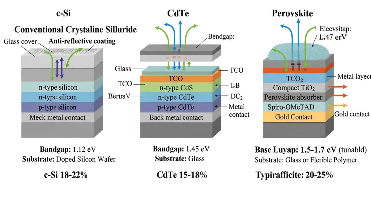
Solar Panels Explained: Photovoltaic energy conversion relies on the creation of an electric field within a semiconductor, typically silicon, to generate electron flow when exposed to photons. The efficiency of this process is dictated by the bandgap energy of the material and the internal resistance of the cell architecture.
At the heart of the system is the P-N junction. When photons strike the silicon, they dislodge electrons, creating electron-hole pairs. The internal electric field at the junction forces these electrons toward the N-type layer, creating a potential difference. In my experience, the primary challenge is minimizing recombination losses, where electrons fall back into holes before they can be harvested as current.
Monocrystalline vs. Polycrystalline Architecture
Monocrystalline panels are manufactured from a single crystal structure, resulting in high purity and efficiency, often exceeding 22%. The Czochralski process used to grow these ingots ensures a uniform lattice, which minimizes electron scattering. Conversely, polycrystalline panels are cast from multiple silicon fragments. While cheaper, the grain boundaries between crystals act as traps for charge carriers, reducing overall efficiency to the 15-17% range.
Engineering Limitation: Temperature Sensitivity
All silicon-based PV cells suffer from a negative temperature coefficient. As the module temperature rises above the standard test condition of 25 degrees Celsius, the voltage drops significantly. For every degree increase, you can expect a power loss of approximately 0.3% to 0.5%. In high-ambient-temperature environments, selecting modules with a lower temperature coefficient is more critical than selecting modules with a higher nominal peak power rating.
Thin-Film and Emerging Technologies
Thin-film modules, such as Cadmium Telluride (CdTe) or Copper Indium Gallium Selenide (CIGS), offer a different set of performance characteristics. They are deposited in thin layers onto flexible substrates, making them ideal for building-integrated photovoltaics (BIPV). While their efficiency is lower, they exhibit superior performance in low-light conditions and high-temperature environments compared to crystalline silicon.
When calculating the system output, we must account for the Performance Ratio (PR). The PR is the ratio of the actual energy yield to the theoretical yield based on the site’s irradiance. A well-designed system should maintain a PR between 0.75 and 0.85. Factors affecting this include shading, inverter efficiency, and cable losses, which must be calculated using NEC guidelines for voltage drop and conductor sizing.
Solar Panel Performance Trade-offs: Evaluating the technical merits and operational limitations of various photovoltaic technologies for industrial deployment.
Advantages
- High power density of monocrystalline cells minimizes land footprint.
- Long operational lifespan, often exceeding 25 years with minimal degradation.
- Scalable modular design allows for incremental capacity expansion.
- Low maintenance requirements due to the absence of moving parts.
- Thin-film flexibility enables installation on non-traditional surfaces.
Disadvantages
- High initial capital expenditure for high-efficiency monocrystalline modules.
- Performance degradation due to high ambient temperatures.
- Intermittency issues requiring robust energy storage or grid balancing.
- Sensitivity to shading, where a single shaded cell can drop string voltage.
- Environmental impact of manufacturing processes and material disposal.
Industrial Solar Integration: Deploying photovoltaic solutions across diverse sectors to optimize energy consumption and reduce carbon intensity.
Utility-Scale Power Generation
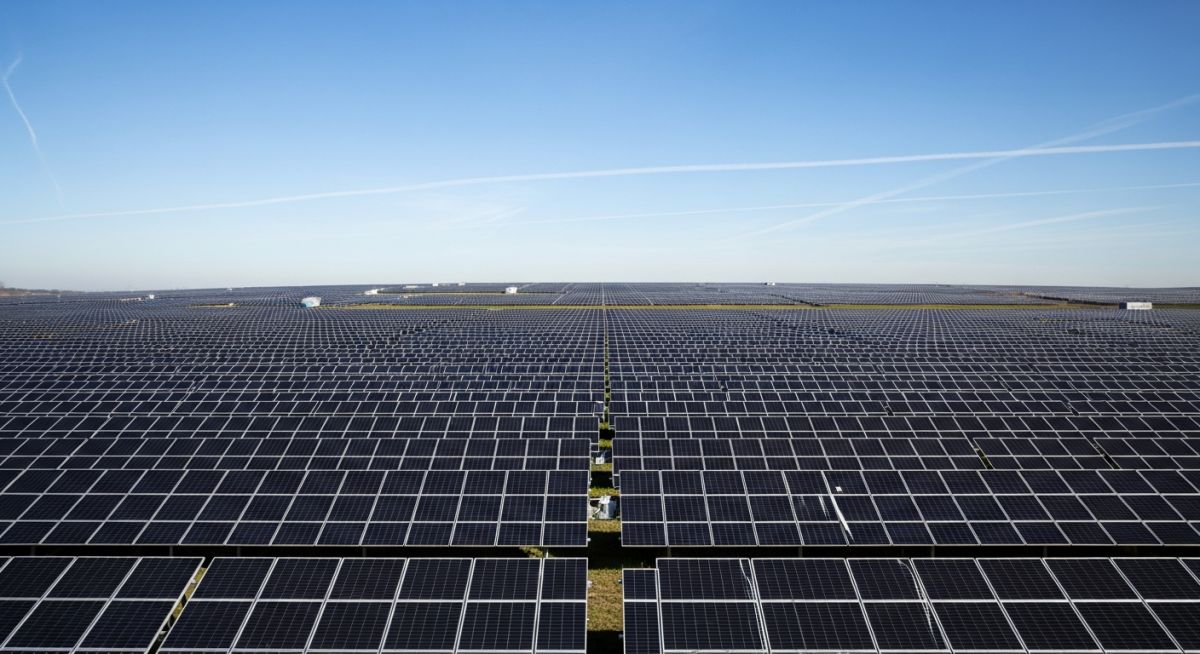
Large-scale solar farms utilize high-efficiency monocrystalline arrays to maximize energy yield per acre. These systems are integrated into the high-voltage grid, requiring sophisticated power conversion and synchronization equipment to maintain grid stability.
Industrial Facility Decarbonization
Manufacturing plants install rooftop solar arrays to offset peak demand charges and reduce reliance on fossil-fuel-based grid power. This application focuses on load matching, where the solar generation profile is aligned with the facility’s operational hours.
Remote Off-Grid Infrastructure
In remote oil and gas or mining operations, solar panels provide reliable power for cathodic protection, instrumentation, and telemetry. These systems are designed for extreme environmental resilience and often incorporate battery storage for 24/7 operation.
Selecting the appropriate photovoltaic technology requires a granular understanding of how different cell architectures respond to environmental variables. In my experience, engineers often focus solely on peak power output, yet the temperature coefficient and degradation rates are the true determinants of long-term system viability. The following table provides a comparative analysis of the three primary panel technologies, highlighting the critical performance metrics that dictate their suitability for specific industrial and residential applications.
When reviewing these values, note that efficiency ratings are based on Standard Test Conditions (STC) defined by IEC 61215. These metrics serve as a baseline for system sizing, but they must be adjusted for site-specific irradiance profiles and ambient temperature fluctuations. Always cross-reference these manufacturer-provided data points with independent field testing to ensure the selected module maintains its performance integrity over a 25-year operational lifespan.
| Technology | Efficiency Range | Temp Coefficient | Lifespan |
|---|---|---|---|
| Monocrystalline | 19% – 23% | -0.35%/C | 25-30 Years |
| Polycrystalline | 15% – 17% | -0.40%/C | 20-25 Years |
| Thin-Film (CdTe) | 10% – 13% | -0.25%/C | 15-20 Years |
The integration of solar energy systems into modern electrical grids necessitates a rigorous mapping of physical components to their respective regulatory standards. This matrix organizes the core entities involved in photovoltaic design, from the semiconductor material level to the balance-of-system (BOS) components. Understanding these relationships is vital for engineers tasked with procurement, system integration, and long-term maintenance planning.
Each entity listed below is governed by specific international codes that ensure safety, interoperability, and performance consistency. By aligning your project specifications with these recognized standards, you mitigate the risk of component failure and ensure compliance with local grid connection requirements. This mapping serves as a foundational reference for technical documentation and site-specific design audits.
Solar Panel Selection Criteria: Before finalizing the procurement of solar modules, a comprehensive site verification process is mandatory. This checklist ensures that the selected technology aligns with the physical, environmental, and electrical constraints of the project site. Failure to account for these variables often leads to significant performance shortfalls and increased maintenance costs over the system’s operational life.
- 01. Irradiance Analysis: Verify the annual solar resource data using NREL PVWatts to ensure the site meets the minimum threshold for project ROI.
- 02. Shading Assessment: Conduct a 3D shading analysis to identify potential obstructions from vegetation, neighboring structures, or future developments.
- 03. Structural Integrity: Confirm that the roof or ground mounting system complies with ASCE 7-16 wind and snow load requirements for the specific geographic region.
- 04. Thermal Management: Evaluate the ambient temperature profile to select modules with an appropriate temperature coefficient, minimizing power loss during peak summer months.
- 05. Grid Compatibility: Ensure the inverter and module string voltage configurations align with local utility interconnection standards and NEC Article 690.
Once these parameters are verified, document the findings in a formal site assessment report. This documentation is essential for securing project financing and obtaining necessary permits from local authorities. Always prioritize modules that offer extended performance warranties and have a proven track record in similar climatic conditions.
Problem: High-Temperature Performance Degradation
A 500kW industrial rooftop installation in a desert climate experienced a 15% drop in expected energy yield during the summer months due to excessive module heating.
- Inadequate ventilation between the roof surface and the module array.
- Selection of polycrystalline modules with high negative temperature coefficients.
- Lack of thermal dissipation planning in the initial design phase.
- High ambient temperatures exceeding 45 degrees Celsius.
Outcome: Optimized Thermal Management Strategy
The project team retrofitted the array with high-efficiency monocrystalline modules featuring lower temperature coefficients and improved mounting brackets for better airflow.
- Achieved a 12% increase in total annual energy production.
- Reduced operating temperatures by 8 degrees Celsius through improved convection.
- Enhanced system reliability and reduced long-term degradation rates.
- Successfully met the projected ROI targets within the first 24 months.
The recommendation for future projects is to conduct a detailed thermal simulation during the design phase. By selecting modules with superior temperature coefficients and ensuring adequate mounting clearance, engineers can significantly improve the performance of solar installations in high-heat environments.
How does the temperature coefficient affect solar panel output?
- Higher coefficients lead to significant power loss in hot climates.
- Monocrystalline panels generally offer better thermal stability than polycrystalline alternatives.
- Engineers must calculate the expected operating temperature to accurately size the inverter and string configurations.
- Refer to IEC 61215 for standardized testing procedures regarding thermal performance.
What is the difference between monocrystalline and polycrystalline panels?
- Monocrystalline panels occupy less space for the same power output.
- Polycrystalline panels are manufactured by melting multiple silicon fragments, making them more cost-effective but slightly less efficient.
- The choice between them depends on the available surface area and the project budget.
- Both technologies are subject to the same rigorous UL 1741 safety standards.
Why is thin-film technology used in specific industrial applications?
- They are less sensitive to partial shading compared to crystalline modules.
- The manufacturing process allows for integration into building materials, such as solar shingles or glass.
- While efficiency is lower, the total energy yield in specific environments can be competitive.
- Always verify the degradation rates, as thin-film modules may have shorter lifespans than crystalline counterparts.
How do I determine the correct inverter size for my array?
- A common design practice is to oversize the DC array by 10% to 20% relative to the inverter capacity.
- This ensures the inverter operates near its maximum efficiency point for a longer duration throughout the day.
- Consult the manufacturer’s datasheet for the maximum input voltage and current limits.
- Ensure compliance with NEC Article 690 regarding overcurrent protection and disconnect requirements.
What are the primary causes of solar panel degradation?
- Potential Induced Degradation (PID) caused by high voltage stress between the cells and the frame.
- Thermal cycling, which causes mechanical stress on the solder joints and interconnects.
- UV exposure leading to the yellowing of the encapsulant material over time.
- Moisture ingress due to compromised seals, which can lead to corrosion of the internal circuitry.
How do I ensure compliance with local grid interconnection standards?
- Verify that the inverter is certified to UL 1741 for grid-interactive operation.
- Ensure the system includes a visible, lockable AC disconnect switch for utility personnel.
- Submit a single-line diagram that clearly shows the point of common coupling and protection devices.
- Coordinate with the local utility to confirm the capacity of the distribution transformer to handle the exported power.
