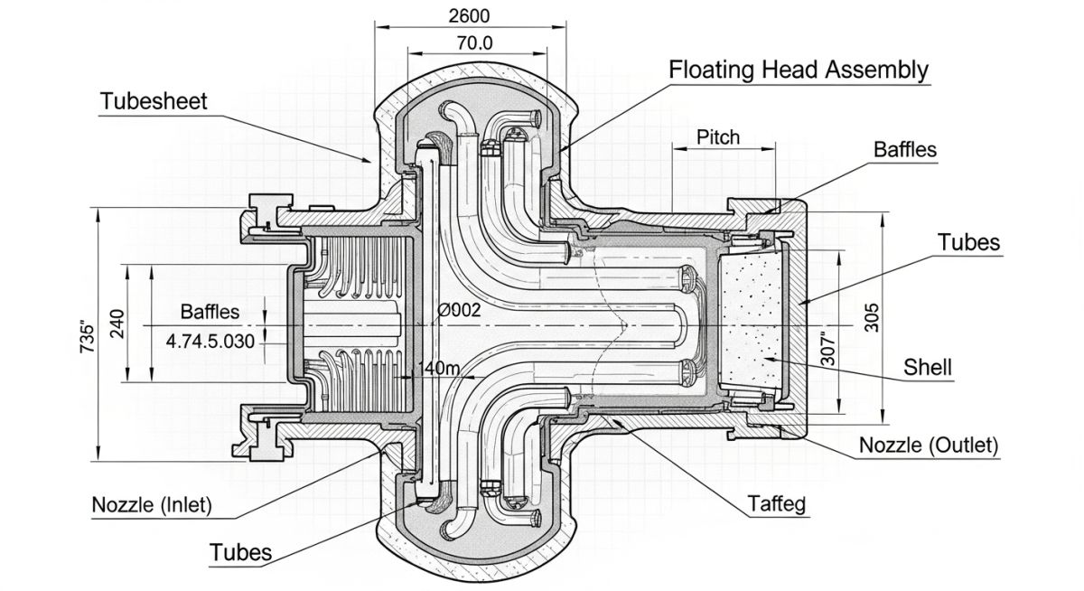
Check List for Reviewing of Shell & Tube Heat Exchanger Drawings
In my two decades of experience, I have seen far too many projects delayed by simple oversights in heat exchanger fabrication drawings. A shell and tube heat exchanger is not merely a pressure vessel; it is a complex thermal machine where nozzle orientation, baffle spacing, and tube-to-tubesheet joint integrity dictate the entire plant’s reliability. When I review these drawings, I look beyond the basic dimensions to ensure the design accounts for differential thermal expansion, flow-induced vibration, and maintenance accessibility.
This guide provides a rigorous framework for engineers to validate every critical aspect of the drawing package. By following this checklist, you move from passive observation to active technical oversight, catching potential failures before they reach the shop floor.
Key Takeaways for Your Review:
- Verify nozzle projections against piping GA drawings to prevent field rework.
- Confirm TEMA class compliance for baffle clearances and tube pitch geometry.
- Validate weld joint categories and NDE requirements per ASME Section VIII.
- Check for proper venting and draining locations based on process fluid properties.
Technical Review of Shell and Tube Heat Exchanger Drawings
Exchanger Drawing Compliance: The rigorous verification of mechanical design parameters, material specifications, and geometric tolerances against ASME BPVC and TEMA requirements to ensure safe operation under specified process conditions.
When performing a deep-dive review, I start with the pressure boundary components. The shell thickness calculation must account for the corrosion allowance specified in the process data sheet. I verify that the shell diameter is sufficient to accommodate the tube bundle while maintaining the required TEMA clearances. If the design is a U-tube configuration, I pay special attention to the bend radius and the minimum wall thickness at the extrados, which is often thinned during the bending process.
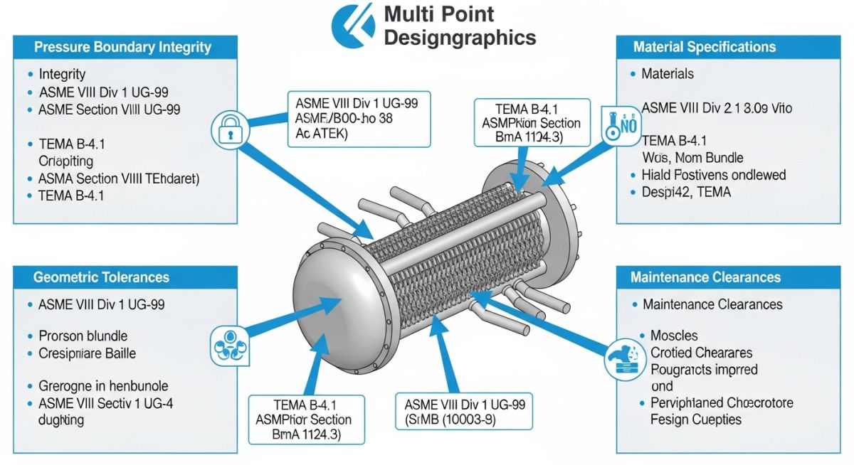
Tubesheet and Nozzle Integrity
The tubesheet is the heart of the exchanger. I check the ligament efficiency calculations to ensure that the remaining metal between tube holes is sufficient to withstand the differential pressure between the shell side and tube side. If the drawing shows a fixed tubesheet design, I look for the expansion joint details; without these, the thermal stress on the tubes will inevitably lead to joint failure.
Critical Warning: Nozzle Loading
Always cross-reference the nozzle loads provided by the piping stress team with the vendor’s drawing. If the vendor has not accounted for external piping moments, the shell wall thickness at the nozzle junction may be insufficient, leading to localized buckling or flange leakage during operation.
Baffle and Support Geometry
Baffle spacing is critical for both heat transfer efficiency and flow-induced vibration (FIV) mitigation. I verify that the baffle cut percentage aligns with the thermal design software output. If the vibration analysis indicates a risk, I look for additional support plates or reduced baffle spacing in the inlet nozzle regions to prevent tube-to-baffle wear.
Finally, I review the weld details. Every pressure-retaining weld must be clearly identified with a joint category (A, B, C, or D) as per ASME Section VIII Div 1. I ensure that the NDE (Non-Destructive Examination) requirements, such as Radiographic Testing (RT) or Ultrasonic Testing (UT), are explicitly noted on the drawing for each category.
Drawing Review Methodology: A structured approach to identifying design discrepancies early, balancing the benefits of rigorous verification against the time-intensive nature of detailed engineering audits.
Advantages
- Prevents costly field modifications by identifying nozzle interference early.
- Ensures strict adherence to ASME pressure boundary safety factors.
- Reduces long-term maintenance costs by verifying accessibility for tube cleaning.
- Validates that thermal expansion provisions are correctly integrated into the design.
- Standardizes quality control across different equipment vendors.
Disadvantages
- Requires significant man-hours from senior engineering staff.
- Can lead to project schedule delays if vendor responses are slow.
- Risk of “over-engineering” if reviewers deviate from project specifications.
- High complexity in coordinating multi-disciplinary comments (piping, process, mechanical).
- Potential for misinterpretation of complex TEMA geometric requirements.
Engineering Application Scope: The deployment of standardized drawing review protocols across diverse industrial sectors to maintain mechanical integrity in high-pressure and high-temperature environments.
Refinery Crude Distillation Units
In crude units, heat exchangers operate under severe fouling conditions. Reviewing drawings for these units requires verifying that the tube pitch and baffle design allow for mechanical cleaning tools, ensuring the exchanger can be maintained without requiring a full bundle pull-out during every turnaround.
High-Pressure Hydrogen Service
When reviewing exchangers for hydrogen service, the focus shifts to material compatibility and weld integrity to prevent hydrogen embrittlement. I verify that the drawing specifies the correct post-weld heat treatment (PWHT) and that the weld joint design minimizes stress concentrations that could initiate cracking.
Cryogenic Gas Processing
For cryogenic applications, the drawing review must confirm the use of low-temperature impact-tested materials. I pay close attention to the thermal contraction details, ensuring that the shell and tube bundle can move independently without inducing excessive stress on the tubesheet-to-shell weld.
Power Plant Feedwater Heaters
Feedwater heaters are subject to cyclic thermal loading during plant startup and shutdown. My review process here emphasizes the fatigue analysis documentation and the integrity of the tube-to-tubesheet joints, which are the most common failure points in high-pressure steam service.
When performing a technical review of shell and tube heat exchanger drawings, I prioritize the alignment between the mechanical design and the process data sheet. Discrepancies here often lead to catastrophic failures during hydrostatic testing or premature fatigue during thermal cycling. The following table outlines the primary design parameters that must be verified against ASME BPVC Section VIII Division 1 requirements.
Engineers must ensure that the design pressure and temperature ratings are not only consistent across the shell and tube sides but also account for the most severe coincident conditions. Pay close attention to the corrosion allowance specified for each component, as this directly impacts the minimum required thickness calculations for the shell, tubesheet, and nozzle necks.
| Parameter | ASME Reference | Review Focus |
|---|---|---|
| Shell Thickness | UG-27 | Verify minimum thickness after corrosion allowance. |
| Tubesheet Design | UHX-12 | Check ligament efficiency and bending stress. |
| Nozzle Reinforcement | UG-37 | Ensure area replacement meets pressure requirements. |
| Flange Rating | Appendix 2 | Confirm bolt load and gasket seating stress. |
Always cross-reference these values with the TEMA standards if the project specifies them, as TEMA often imposes stricter geometric constraints than the base ASME code. A failure to reconcile these standards early in the drawing review phase will inevitably result in costly field modifications.
The following matrix maps the critical physical entities of a shell and tube heat exchanger to their respective engineering standards and design constraints. In my experience, the most common oversight occurs when the interaction between the tube bundle and the shell baffle arrangement is ignored during the initial drawing review.
This matrix serves as a quick-reference guide for verifying that all structural components are accounted for in the fabrication drawings. Each entity listed must be checked for material compatibility, weld joint efficiency, and accessibility for future maintenance activities such as tube cleaning or bundle extraction.
| Component | Standard | Key Metric |
|---|---|---|
| Baffles | TEMA RCB-4 | Baffle spacing and cut percentage. |
| Expansion Joint | ASME VIII-1 App 5 | Cycle life and spring rate. |
| Tube-to-Tubesheet | ASME VIII-1 UW-20 | Weld strength and leak path. |
| Saddles/Supports | ASME VIII-1 UG-22 | Load distribution and seismic rating. |
By maintaining this mapping, you ensure that the design review remains systematic. Always verify that the ASME code edition referenced on the drawing matches the project specification, as updates to the code can significantly alter the required safety factors for support structures.
Reviewing shell and tube heat exchanger drawings requires a disciplined approach to ensure that the physical reality of the plant site matches the theoretical design. I have developed this checklist to prevent common installation errors that often arise from misaligned nozzle orientations or insufficient clearance for maintenance.
-
[ ]
Nozzle Orientation: Verify that all nozzle centerlines align with the piping isometric drawings to avoid field-fit issues. -
[ ]
Maintenance Clearance: Confirm that the bundle pull space is clear of structural steel, cable trays, and other piping. -
[ ]
Support Alignment: Check that the saddle locations match the foundation bolt patterns provided by the civil engineering team. -
[ ]
Lifting Lugs: Ensure that the lifting lug design is rated for the full weight of the exchanger, including the bundle. -
[ ]
Drain and Vent: Verify that drain and vent connections are located at the high and low points of the shell and tube sides.
Before signing off on the final drawing package, perform a final walkthrough of the 3D model if available. Cross-check the ASME nameplate data against the drawing title block to ensure that the design pressure and temperature are correctly documented for the end-user. Any deviation in these critical parameters must be formally addressed through a technical query or a design change notice.
Problem: Misaligned Bundle Extraction Path
- The drawing review failed to account for a structural column installed after the initial layout.
- The bundle pull space was reduced by 1.5 meters, making it impossible to remove the tube bundle.
- The error was only discovered during the first scheduled turnaround, leading to a 48-hour plant shutdown extension.
- The cost of cutting and relocating the structural steel exceeded the original fabrication cost of the exchanger.
Outcome: Corrective Action and Process Improvement
- Implemented a mandatory 3D model clash detection check for all maintenance access paths.
- Updated the drawing review checklist to include a physical site verification step for all major equipment.
- Established a cross-functional review meeting between piping, structural, and maintenance departments.
- Reduced future maintenance downtime by 20% through improved spatial awareness in the design phase.
This case highlights why the review of shell and tube heat exchanger drawings cannot be limited to pressure boundary calculations. You must consider the entire lifecycle of the equipment, including the logistical challenges of maintenance and site integration. Always prioritize the “maintainability” of the design as much as its structural integrity.
How do I verify the tube-to-tubesheet joint strength?
- Check the minimum weld throat thickness against the calculated pressure load.
- Verify that the tube expansion method (if used) is clearly specified on the drawing.
- Ensure that the joint efficiency factor is applied correctly in the tubesheet thickness calculation.
- Confirm that the post-weld heat treatment (PWHT) requirements are noted if the material thickness exceeds the code threshold.
What is the significance of the TEMA class in drawing reviews?
- Class R is for severe service, requiring the most stringent design and inspection standards.
- Class C is for moderate service, often used in general industrial applications.
- Class B is for chemical service, focusing on specific corrosion and material requirements.
- Always verify that the drawing notes explicitly state the TEMA class, as this dictates the allowable tolerances for baffle spacing and tube pitch.
How should I handle nozzle reinforcement calculations?
- Verify that the area of reinforcement provided is greater than or equal to the area required.
- Check that the weld sizes for the reinforcing pad are sufficient to transfer the load.
- Ensure that the tell-tale hole in the reinforcing pad is not plugged, allowing for leak detection.
- Confirm that the nozzle neck thickness is adequate for the specified pressure and temperature.
What are the common pitfalls in expansion joint design?
- Ensure the spring rate is compatible with the shell and tube side differential thermal expansion.
- Verify the cycle life rating against the expected number of thermal cycles during the plant life.
- Check that the expansion joint is protected from external damage during transport and installation.
- Confirm that the material of the bellows is compatible with the process fluid to prevent stress corrosion cracking.
How do I validate the hydrostatic test pressure?
- Always verify the test pressure calculation against the lowest stress ratio of all components.
- Ensure the drawing specifies the test medium (usually water) and any required additives for corrosion inhibition.
- Check that the test pressure is clearly marked on the nameplate and the drawing.
- Verify that the exchanger supports are designed to handle the weight of the test fluid.
Why is baffle spacing critical for vibration?
- Review the baffle spacing against the TEMA vibration analysis guidelines.
- Ensure that the baffle cut is optimized to minimize dead zones while maintaining structural support.
- Check that the tube-to-baffle hole clearance is within the specified tolerances to prevent tube fretting.
- Verify that the inlet and outlet nozzles have adequate impingement protection to prevent direct flow impact on the tubes.
📚 Recommended Resources: Shell and Tube Heat Exchanger
Read these Guides
🎓 Advanced Training


Complete Course on
Piping Engineering
Check Now
Key Features
- 125+ Hours Content
- 500+ Recorded Lectures
- 20+ Years Exp.
- Lifetime Access
Coverage
- Codes & Standards
- Layouts & Design
- Material Eng.
- Stress Analysis
