How Rotary Selector Valve and Multi Phase Flow Meter Systems Optimize Production
In my 20-plus years of designing piping manifolds and well-testing systems, I have seen operators struggle with massive, heavy test separators on offshore platforms and tight onshore pads. The traditional approach of routing individual flowlines through a complex matrix of isolation valves, bypass lines, and headers is not only expensive but also a maintenance nightmare.
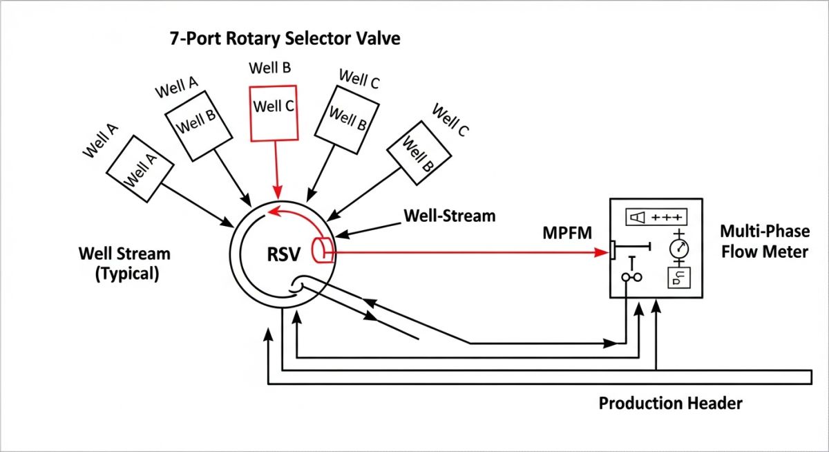
By combining a multiport selector valve with a multiphase flow meter, we completely transform this landscape. This integrated system allows you to select any single well for testing while the remaining wells continue to flow uninterrupted to the main production header. In this guide, I will share my field-tested insights on how to design, size, and commission these systems to achieve maximum reliability and measurement accuracy.
Key Engineering Takeaways
- Footprint Reduction: Replaces up to 14 isolation valves and a massive test separator vessel with a single compact valve and meter skid.
- Real-Time Data: Delivers continuous, transient-free flow rate measurements for oil, water, and gas without requiring physical fluid separation.
- Lower CAPEX & OPEX: Minimizes piping runs, structural steel support requirements, and automated valve actuator counts.
- Automated Testing: Enables seamless, programmable well-switching sequences directly from the control room.
Integrating Rotary Selector Valve and Multi Phase Flow Meter
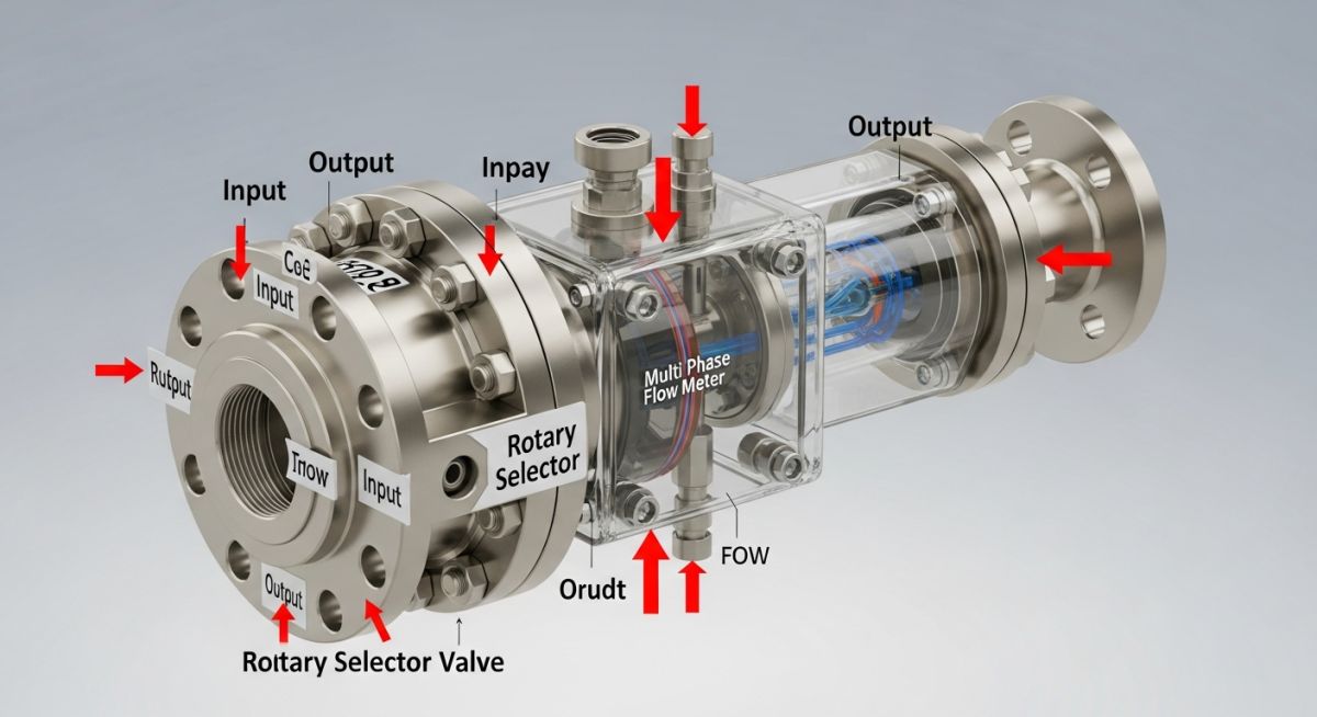
The mechanical heart of this system is the Rotary Selector Valve (RSV), often referred to as a Multiport Selector Valve (MSV). It typically features seven or eight inlet ports and two outlet ports: one dedicated test outlet and one main production outlet. Inside the valve, a rotatable selector plug or rotor aligns a single inlet port with the test outlet. The remaining inlet ports vent directly into the valve body casing, which drains into the main production outlet.
The fluid from the selected well is routed directly to the Multi Phase Flow Meter (MPFM). Unlike traditional test separators that rely on gravity settling to separate oil, water, and gas phases over several hours, the MPFM utilizes a combination of physical sensors to measure the individual phase flow rates in real time. This is achieved by combining a Venturi tube for total mass flow rate measurement with a dual-energy gamma-ray densitometer or electrical impedance sensors to determine phase fractions.
Pressure Drop and Sizing Calculations
When sizing the selector valve and the multiphase meter, we must carefully balance the pressure drop across the system. Excessive pressure drop can cause dissolved gases to flash out of the liquid phase prematurely, leading to severe measurement errors in the flow meter and potential cavitation within the valve.
The pressure drop across the rotary selector valve is calculated using the modified Darcy-Weisbach equation:
Where:
• Delta P is the pressure drop across the valve (Pascals)
• K is the dimensionless resistance coefficient of the internal rotor channel (typically ranging from 1.5 to 2.5 depending on the valve model)
• rho is the mixed fluid density (kilograms per cubic meter)
• v is the flow velocity through the selector channel (meters per second)
• gc is the gravitational conversion factor
For a 4-inch selector valve handling a wet gas stream with a mixed density of 85 kilograms per cubic meter and a velocity of 12 meters per second, with a K-factor of 1.8, the pressure drop is calculated as: Delta P = 1.8 * (85 * 12^2) / 2 = 11,016 Pascals (11.02 kPa). This low pressure drop is critical to prevent flashing of light hydrocarbons before they reach the multiphase flow meter.
The sizing of the Venturi nozzle within the multiphase flow meter relies on the Lockhart-Martinelli parameter (X) to evaluate the liquid-to-gas ratio:
Where m_L and m_G are the mass flow rates of liquid and gas, and rho_L and rho_G are their respective densities. To maintain measurement accuracy within the +/- 5% relative error band specified by API RP 86, the throat-to-inlet diameter ratio (beta) of the Venturi must be selected between 0.4 and 0.6.
Technical Specifications for Selector Manifolds
Selecting the correct materials and pressure ratings is critical when integrating these systems into sour or high-temperature production environments. Below are the standard engineering parameters I use during the front-end engineering design (FEED) phase.
| Parameter | Standard Specification | Design Code Reference | Engineering Notes |
|---|---|---|---|
| Pressure Rating | ASME Class 150 to Class 2500 / API 5000 to 15000 | ASME B16.34 / API 6A | Must match upstream wellhead shut-in pressure. |
| Body Materials | Super Duplex SS (UNS S32750) / Carbon Steel + Inconel 625 Clad | ASTM A995 / ASTM A350 | Inconel cladding is preferred for high H2S and CO2 service. |
| Sealing Mechanism | Metal-to-Metal with Tungsten Carbide Coating (TCC) | ISO 5208 Rate A | Ensures zero bubble-tight leakage during well isolation. |
| Actuator Type | Electro-Hydraulic or Intelligent Electric Actuator | IEC 60079 / ATEX | Requires precise positioning feedback within 0.5 degrees. |
To ensure seamless integration between the mechanical selector valve and the electronic multiphase flow meter, use this technical mapping matrix to align your instrumentation and piping interfaces.
| System Component | Acronym | Primary Physical Parameter | Applicable Standard |
|---|---|---|---|
| Rotary Selector Valve | RSV / MSV | Flow Routing & Isolation Differential Pressure | API Spec 6D |
| Multi Phase Flow Meter | MPFM | Phase Fraction & Volumetric Flow Rates | API RP 86 |
| Gas Volume Fraction | GVF | Gas-to-Total Fluid Ratio at Line Conditions | ISO/TR 11583 |
| Water Liquid Ratio | WLR | Water Cut within the Liquid Phase | ASTM D4007 |
Field Commissioning Steps for Selector Systems
During my time on commissioning sites, I have found that most start-up failures stem from poor actuator calibration or incorrect fluid property inputs in the MPFM software. Use this checklist to verify your installation before introducing live hydrocarbons.
Pre-Commissioning & Site Acceptance Checklist
-
Mechanical Alignment Verification: Confirm that the selector valve rotor aligns perfectly with each inlet port. Misalignment by even 2 degrees can cause severe throttling and localized erosion.
-
Hydrostatic Leak Testing: Perform a shell and seat leak test at 1.5 times the design pressure in accordance with ASME B31.3. Verify zero leakage across the selector seal.
-
Actuator Torque Profile: Record the breakaway and running torque of the actuator. A sudden spike in torque indicates debris or damage to the internal sealing surfaces.
-
MPFM PVT Calibration: Input the correct Pressure-Volume-Temperature (PVT) fluid models into the flow meter flow computer. This must be updated with fresh laboratory PVT data from recent well samples.
-
ESD Loop Integration: Verify that the selector valve actuator and MPFM transmitter are fully integrated into the facility Emergency Shutdown (ESD) system per API RP 14C.
Operating Rotary Selector Valve and Multi Phase Flow Meter
Field Case Study: Real-World Application
We replaced the entire conventional test manifold and separator vessel with a single integrated skid featuring an 8-inch, 1500# Rotary Selector Valve coupled with a dual-energy gamma-ray Multiphase Flow Meter.
This modification reduced the footprint by 82% (down to 27 square meters) and cut the dry weight to just 18 tons. Because the MPFM provides instantaneous, real-time measurements, the stabilization time was eliminated. The operator can now run automated 45-minute test sequences for all 12 wells sequentially within a single 12-hour shift, allowing immediate detection of water breakthrough in individual wells.
Based on this project, my direct recommendation is to always design the bypass loop around the MPFM. This allows you to perform maintenance or sensor calibration on the flow meter without shutting in the well currently selected for testing.
Frequently Asked Engineering Questions
What is the typical design life of a Rotary Selector Valve seal?
Can an MPFM handle extremely high Gas Volume Fractions (GVF > 98%)?
How do you detect internal leakage in a Rotary Selector Valve?
What are the piping straight-run requirements upstream of an MPFM?
How does fluid viscosity affect the accuracy of the multiphase meter?
Is a radioactive source license required for all MPFMs?
===`
Complete Course on
Piping Engineering
Check Now
Key Features
- 125+ Hours Content
- 500+ Recorded Lectures
- 20+ Years Exp.
- Lifetime Access
Coverage
- Codes & Standards
- Layouts & Design
- Material Eng.
- Stress Analysis



