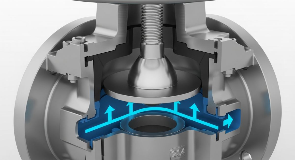
What is a Globe Valve and How Does It Work?
In my 20+ years of piping engineering, I have seen many operators mistake a globe valve for a gate valve, leading to catastrophic cavitation and seat erosion. Let me tell you, understanding the internal mechanics of this workhorse is what separates a reliable plant design from an operational nightmare. While gate valves are strictly for isolation, the globe valve is designed to handle the harsh realities of throttling and flow regulation.
Whether you are managing high-pressure steam lines or handling corrosive chemical processes, selecting the correct globe valve configuration is paramount. In this guide, I will break down the internal components, flow dynamics, and practical engineering considerations that I use daily to specify these valves for heavy industrial projects.
Key Engineering Takeaways
- Understand the distinct flow path differences between T-pattern, Y-pattern, and Angle-pattern designs to minimize pressure drop.
- Learn how to calculate the flow coefficient (Cv) to prevent cavitation and flashing in high-velocity throttling applications.
- Identify the critical internal parts, including the plug, seat, and stem, to ensure correct material selection for corrosive services.
How Does a Globe Valve Regulate Flow?
The fundamental operating principle of a globe valve involves the perpendicular movement of the disc toward or away from the seat. This linear motion creates a symmetric, annular opening that changes size as the handwheel or actuator rotates. Unlike gate valves, where the fluid shear acts perpendicular to the gate face, the fluid in a globe valve strikes the disc head-on or flows around it, distributing the kinetic energy more evenly.
To calculate the flow capacity and pressure drop across a globe valve, engineers rely on the flow coefficient (Cv). The relationship is expressed by the standard formula:
Where:
– Cv is the valve flow coefficient (gallons per minute of water at 60 degrees Fahrenheit with a 1 psi pressure drop).
– Q is the volumetric flow rate in gallons per minute (gpm).
– SG is the specific gravity of the process fluid (dimensionless).
– delta P is the pressure drop across the valve in pounds per square inch (psi).
Because the fluid must change direction multiple times within the valve body (making a double 90-degree turn in a standard T-pattern), the resistance to flow is significantly higher than in a ball or gate valve. This results in a high permanent pressure loss, which must be factored into your overall system hydraulics.
Never install a standard globe valve in high-slurry services or applications with extreme pressure drops without anti-cavitation trim. The tortuous flow path creates localized low-pressure zones where vapor bubbles form and collapse, leading to rapid seat erosion, severe vibration, and complete valve seizure.
When specifying these valves under ASME B16.34, you must also consider the stem force required to close the valve against line pressure. The operating torque increases dramatically with larger nominal diameters and higher pressure classes, often requiring gear operators or pneumatic actuators for sizes above 6 inches.
Standard Dimensions of a Globe Valve
The table below outlines the standard face-to-face dimensions for flanged-end globe valves in accordance with ASME B16.10. These values are critical for piping designers when laying out piping manifolds and calculating structural support loads.
| Nominal Size (Inches) | Class 150 Face-to-Face (mm) | Class 300 Face-to-Face (mm) | Class 600 Face-to-Face (mm) | Est. Weight Class 150 (kg) |
|---|---|---|---|---|
| 2″ | 203 | 267 | 292 | 22 |
| 3″ | 241 | 318 | 356 | 38 |
| 4″ | 292 | 356 | 432 | 58 |
| 6″ | 406 | 444 | 559 | 110 |
| 8″ | 495 | 559 | 660 | 195 |
Selecting the correct material combination (trim) is critical to preventing galvanic corrosion and galling between moving parts. The matrix below maps the primary components of an industrial globe valve to their standard material specifications under ASTM and API guidelines.
| Component | Standard Material | ASTM Standard | Primary Function | Design Limit / Note |
|---|---|---|---|---|
| Body & Bonnet | Carbon Steel / Stainless Steel | ASTM A216 WCB / A351 CF8M | Pressure containment boundary | Subject to temperature limits per ASME B16.34 |
| Stem | 13% Chrome / 316 SS | ASTM A182 F6a / A276 316 | Transmits linear motion to disc | Must resist high tensile and torsional stress |
| Disc (Plug) | Stellite Faced Carbon Steel | ASTM A105 with Co-Cr-A | Flow control and tight shutoff | Hardfacing required for throttling service |
| Seat Ring | Stellite Faced Steel | ASTM A182 F11 with Stellite | Mating surface for disc seal | Threaded or seal-welded to body |
| Packing | Flexible Graphite | API 622 Certified | Prevents fugitive emissions | Requires periodic adjustment to prevent leaks |
How to Inspect a Globe Valve Onsite
Before any valve is welded or bolted into a piping system, a rigorous quality control check must be performed. In my experience, skipping these basic steps is the leading cause of immediate startup leaks and packing failures. Use this checklist during your next field walkdown to ensure complete compliance.
Pre-Installation Quality Checklist
-
Verify Flow Direction Arrow: Globe valves are unidirectional. Ensure the cast arrow on the valve body matches the process flow direction (typically flow-under-disc for utility services, flow-over-disc for high-temperature steam).
-
Inspect Stem and Packing: Check the stem for scratches, pitting, or bending. Ensure the packing gland bolts are evenly torqued to prevent uneven loading on the graphite packing rings.
-
Validate Material Test Reports (MTRs): Cross-reference the heat numbers stamped on the valve body and bonnet with the mill test certificates to confirm chemical composition and pressure rating.
-
Perform Seat Tightness Check: Rotate the handwheel to ensure smooth operation from fully open to fully closed. If possible, witness a low-pressure air seat test in accordance with API 598.
-
Check Flange Face Integrity: Inspect the raised face or ring-type joint (RTJ) grooves for radial scratches or tool marks that could compromise the gasket seal.
Field Case Study: Real-World Application
The Problem: Severe Cavitation in Boiler Feedwater Bypass
At a combined-cycle power plant, a standard 4-inch Class 600 globe valve with a standard linear plug was installed on a boiler feedwater pump bypass line. The valve operated with an inlet pressure of 1,200 psi and throttled down to 150 psi. Within three months of commissioning, the valve began leaking excessively in the closed position, accompanied by a deafening noise level of 102 dBA. Upon disassembly, we discovered that the plug and seat ring were completely destroyed by cavitation, looking as if they had been sandblasted.
The Solution: Multi-Stage Anti-Cavitation Trim Retrofit
I recommended replacing the standard plug with a multi-stage, cage-guided anti-cavitation trim. This design splits the massive pressure drop into four smaller, controlled stages, keeping the localized pressure above the fluid’s vapor pressure. We also upgraded the trim material to solid Stellite 6 to resist high-velocity erosion.
The results were immediate and highly successful. The noise level dropped from 102 dBA to a safe 78 dBA, well within OSHA limits. More importantly, the retrofitted valve has now been in continuous service for over four years without a single seat leak or packing failure.
My Recommendation: Always perform a detailed cavitation index calculation during the design phase for any globe valve operating with a pressure drop ratio exceeding 0.5.
Frequently Asked Engineering Questions
What is the difference between a globe valve and a gate valve?
Why do globe valves have a high pressure drop?
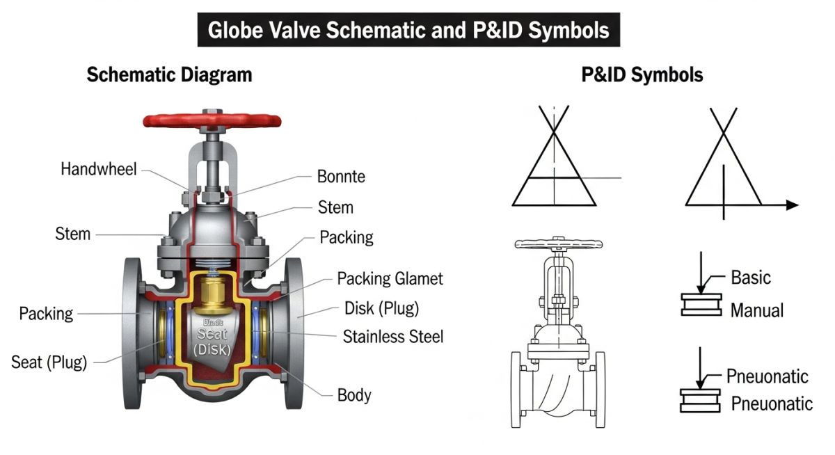
What are the standard symbols for a globe valve in P&ID?
When should you install a globe valve with flow-over-disc?
What is a Y-pattern globe valve and when is it used?
How does API 623 differ from ASME B16.34 for globe valves?
===
Complete Course on
Piping Engineering
Check Now
Key Features
- 125+ Hours Content
- 500+ Recorded Lectures
- 20+ Years Exp.
- Lifetime Access
Coverage
- Codes & Standards
- Layouts & Design
- Material Eng.
- Stress Analysis