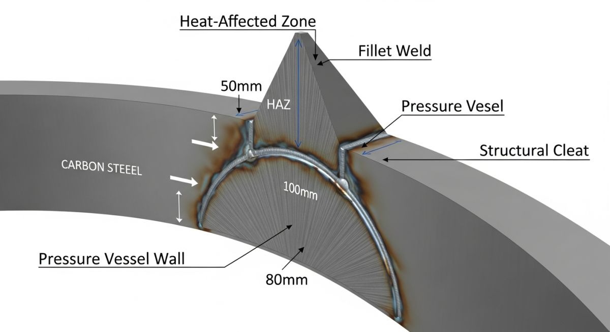
Pressure Vessel Clips: Design and Structural Integrity Standards
In my two decades of field experience, I have seen far too many premature vessel failures caused by poorly engineered attachments. Whether you call them vessel cleats, clips, or lugs, these components are not mere afterthoughts; they are primary load paths that interact directly with the pressure boundary. When we weld a clip to a vessel wall, we introduce localized thermal stresses and geometric discontinuities that can become initiation sites for fatigue cracking or brittle fracture if not calculated correctly.
This guide focuses on the rigorous engineering required to design, specify, and install these attachments. We will move beyond basic geometry to examine how load vectors—thermal expansion, wind, and seismic forces—dictate the sizing and placement of your clips. Proper design ensures that the vessel shell remains the primary pressure-retaining element without compromising its structural stability under operational cycles.
Key Takeaways for Engineering Success:
- Always verify the local stress intensity at the clip-to-shell interface using WRC 107 or 297 bulletins.
- Ensure weld throat thickness accounts for both shear loads and potential prying effects.
- Maintain strict adherence to ASME Section VIII requirements for material compatibility and post-weld heat treatment (PWHT).
- Prioritize the use of “doubler plates” or “reinforcement pads” to distribute concentrated loads over a larger surface area.
Engineering Analysis of Pressure Vessel Clips
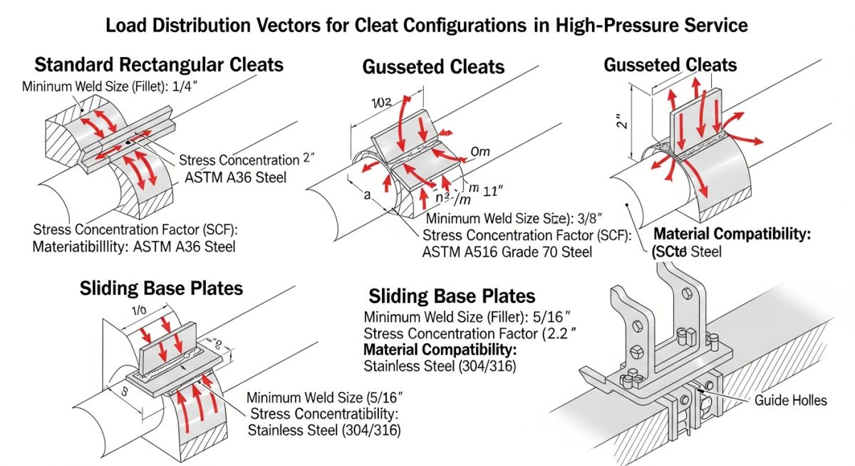
Pressure Vessel Clips Design: These components must be engineered to transfer external loads into the vessel shell while minimizing local stress concentrations that could lead to fatigue or shell deformation. The design process begins with identifying the load path, which typically involves calculating the resultant force from piping thermal expansion, weight of attached platforms, or seismic acceleration.
When designing these attachments, I always start with the ASME Section VIII requirements for non-pressure parts. The primary challenge is the “local stress” effect. Unlike internal pressure, which acts uniformly, a clip creates a point load. We use the Welding Research Council (WRC) bulletins, specifically WRC 107 and WRC 297, to calculate the stress at the junction of the attachment and the shell. The total stress is the sum of the membrane stress and the bending stress induced by the moment arm of the clip.
Critical Design Limitation:
Never weld a clip directly to a pressure-retaining weld seam. The heat-affected zone (HAZ) of the seam is already metallurgically altered; adding a second weld creates a complex stress state that significantly increases the risk of crack propagation. Always maintain a minimum clearance of 50mm or 4 times the shell thickness, whichever is greater, from any longitudinal or circumferential weld.
For load-bearing cleats, the shear stress in the weld is calculated as the force divided by the effective throat area. However, we must also consider the prying action. If the clip is long, the outer edge tends to pull away from the shell, creating a tensile component in the weld. I recommend using a fillet weld profile that provides a smooth transition to reduce the stress concentration factor (SCF). If the calculated stress exceeds the allowable limits defined in the code, the solution is not just increasing the weld size; it is increasing the contact area via a reinforcement pad.
Material selection is equally vital. The clip material should match the vessel shell material to ensure similar coefficients of thermal expansion. If you are working with stainless steel attachments on carbon steel vessels, you must account for the differential expansion, which can induce significant shear stress at the weld interface during thermal cycling. Always verify the impact test requirements if the vessel operates in low-temperature service, as the attachment weldment must meet the same toughness criteria as the pressure boundary.
Structural Attachment Performance: The selection and implementation of vessel clips involve a trade-off between structural rigidity and the preservation of the vessel’s pressure-retaining integrity.
Advantages
- Provides precise, rigid support for piping and insulation systems.
- Allows for modular construction by enabling field-welded attachments.
- Distributes concentrated loads effectively when paired with reinforcement pads.
- Facilitates easy maintenance and replacement of external piping components.
- Enables predictable load paths for seismic and wind analysis.
Disadvantages
- Introduces localized stress concentrations that require complex analysis.
- Creates potential sites for corrosion under insulation (CUI).
- Requires strict adherence to PWHT if the vessel material is sensitive.
- Increases the risk of shell distortion during the welding process.
- Limits the ability to modify vessel internals or external layout later.
Industrial Attachment Deployment: Pressure vessel clips are utilized across diverse sectors to manage mechanical loads and thermal expansion in high-pressure environments.
Refinery Distillation Columns
In large-scale distillation columns, vessel cleats are essential for supporting internal trays and external piping manifolds. These clips must withstand high-temperature fluctuations and vibration, requiring robust fillet welds and careful placement to avoid interfering with the column’s structural shell integrity.
Cryogenic Storage Vessels
For liquefied natural gas (LNG) storage, clips are used to secure insulation support rings and external piping. The design must account for extreme thermal contraction, utilizing materials that maintain ductility at cryogenic temperatures to prevent brittle failure at the attachment point.
High-Pressure Heat Exchangers
Clips are frequently employed on heat exchanger shells to support heavy piping nozzles and maintenance platforms. These attachments are engineered to handle significant moment loads, often utilizing reinforcement pads to ensure the shell thickness remains within the allowable limits defined by ASME standards.
Chemical Reactor Vessels
In reactors subject to cyclic pressure and temperature, clips support external heating or cooling jackets. The attachment design must minimize thermal bridging and stress accumulation, ensuring that the reactor shell remains free from fatigue-induced cracks over the vessel’s operational lifespan.
When designing attachments for pressure vessels, engineers must account for the specific load-bearing capacity of the clip relative to the vessel wall thickness. The following table outlines typical design parameters for standard carbon steel clips, assuming a minimum yield strength of 250 MPa for the attachment material. These values are derived from ASME Section VIII, Division 1, which mandates that the attachment must not compromise the pressure boundary integrity.
It is vital to note that these capacities are theoretical maximums. In practice, the actual allowable load is significantly influenced by the weld throat thickness, the proximity of the clip to a nozzle or flange, and the thermal expansion characteristics of the connected piping system. Always perform a localized stress analysis using finite element methods if the clip is subjected to high-frequency vibration or significant thermal cycling.
| Clip Size (mm) | Max Vertical Load (kN) | Max Lateral Load (kN) | Min Vessel Wall (mm) |
|---|---|---|---|
| 50 x 50 | 12.5 | 5.0 | 6.0 |
| 75 x 75 | 22.0 | 8.5 | 8.0 |
| 100 x 100 | 35.0 | 15.0 | 10.0 |
Engineers should verify that the weld size does not exceed the thickness of the vessel wall to prevent burn-through during fabrication. If the calculated load exceeds these values, a reinforcement pad or a larger clip footprint is required to distribute the stress over a wider surface area, thereby reducing the localized stress concentration factor.
The following matrix provides a technical mapping of the critical entities involved in the design and installation of pressure vessel clips. Understanding the relationship between these components is necessary for compliance with ASME BPVC standards. Each entity plays a specific role in ensuring the structural stability of the vessel under operational conditions.
This matrix serves as a quick-reference guide for project engineers to ensure that all material specifications, welding procedures, and inspection requirements are aligned with the project’s quality assurance plan. By mapping these entities, we minimize the risk of non-conformance during third-party inspections or hydrostatic testing phases.
| Entity | Acronym | Standard Reference | Primary Function |
|---|---|---|---|
| Pressure Vessel | PV | ASME VIII | Containment of pressurized fluids |
| Welding Procedure | WPS | ASME IX | Governs weld quality and integrity |
| Heat Affected Zone | HAZ | API 579 | Area of metallurgical change |
The interaction between the HAZ and the base metal is a critical failure point. Proper pre-heating and post-weld heat treatment (PWHT) are often required when the vessel wall thickness exceeds 25mm, as specified in the ASME Section VIII guidelines for carbon steel attachments.
Verification of pressure vessel clips requires a systematic approach to ensure that the physical installation matches the design intent. In my experience, most field failures occur due to improper weld sizing or the failure to account for thermal expansion gaps. This checklist is designed to guide site inspectors through the critical verification steps required for compliance with ASME Section VIII.
-
1.
Verify that the clip material is compatible with the vessel shell material to prevent galvanic corrosion. -
2.
Check that the weld size matches the approved drawing specifications and that the weld profile is smooth to minimize stress risers. -
3.
Confirm that the clip is not located within the prohibited zones near nozzle welds or longitudinal seams. -
4.
Ensure that all temporary attachments used during construction have been removed and the surface ground flush. -
5.
Perform a visual inspection for cracks or porosity in the weld bead using dye penetrant testing (PT) if required by the project specification.
Site verification is not merely a box-ticking exercise; it is the final line of defense against catastrophic failure. Always document the findings in the project quality log, ensuring that any deviations are signed off by the lead structural engineer. If a clip is found to be misaligned, do not attempt field modifications without a formal Management of Change (MOC) process, as this could invalidate the vessel’s pressure rating.
Problem: Premature Weld Cracking in High-Temperature Service
A major refinery experienced recurring weld cracks at the base of support clips on a high-temperature reactor vessel.
- Thermal expansion mismatch between the clip and the vessel shell.
- Inadequate weld throat thickness leading to fatigue failure.
- Lack of proper pre-heat during the initial installation phase.
- High-frequency vibration from adjacent rotating equipment.
Outcome: Successful Remediation and Structural Integrity Restoration
The engineering team implemented a comprehensive repair strategy that restored the vessel’s structural integrity.
- Replaced rigid clips with slotted designs to accommodate thermal expansion.
- Increased weld throat size and implemented a controlled PWHT cycle.
- Reduced vibration levels through the installation of secondary dampeners.
- Achieved 100% pass rate on subsequent ultrasonic testing (UT) inspections.
The recommendation for similar projects is to prioritize thermal expansion analysis during the design phase. By utilizing flexible attachment designs, we can significantly reduce the stress concentrations that lead to the types of failures observed in this case study. Always consult ASME Section VIII for guidance on attachment design limits.
Frequently Asked Engineering Questions
What is the primary purpose of a pressure vessel clip?
- Facilitate the installation of external piping supports.
- Support insulation jackets and weatherproofing systems.
- Provide mounting points for instrumentation and control panels.
- Ensure load distribution across the vessel shell surface.
How does ASME Section VIII regulate clip welding?
- Weld size must be calculated to prevent base metal damage.
- Attachments must be made of weldable materials compatible with the shell.
- Proximity to pressure-retaining welds must be strictly controlled.
- Post-weld heat treatment requirements must be evaluated based on thickness.
Can I weld clips directly onto the vessel shell?
- Ensure the base metal is pre-heated if required by the material specification.
- Use low-hydrogen electrodes to minimize the risk of hydrogen-induced cracking.
- Avoid welding over existing longitudinal or circumferential seams.
- Perform non-destructive examination (NDE) on the finished weld.
What are the risks of improper clip placement?
- Increased risk of shell deformation under pressure.
- Potential for crack initiation at the weld toe.
- Interference with the vessel’s natural thermal expansion.
- Violation of code-mandated minimum distances from pressure welds.
How do I handle thermal expansion in clip design?
- Calculate the total expansion based on the operating temperature range.
- Use slotted bolt holes to allow for movement in the primary direction.
- Consider the use of PTFE slide plates for heavy piping loads.
- Verify that the support structure can handle the resulting thermal loads.
What NDE methods are recommended for vessel clips?
- Visual Inspection: Mandatory for all weld passes.
- Dye Penetrant Testing (PT): Recommended for detecting surface cracks.
- Magnetic Particle Testing (MT): Effective for ferromagnetic materials.
- Ultrasonic Testing (UT): Used for critical attachments to check for subsurface defects.
📚 Recommended Resources: Pressure Vessel Clips
Read these Guides
🎥 Watch Tutorials

Complete Course on
Piping Engineering
Check Now
Key Features
- 125+ Hours Content
- 500+ Recorded Lectures
- 20+ Years Exp.
- Lifetime Access
Coverage
- Codes & Standards
- Layouts & Design
- Material Eng.
- Stress Analysis