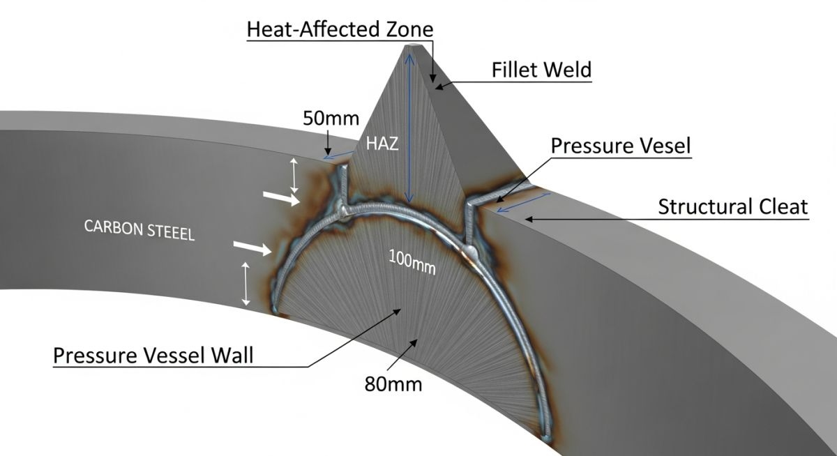
Pressure Vessel Clips: Design and Structural Integrity Standards
In my two decades of field experience, I have seen too many projects suffer from premature vessel wall fatigue caused by poorly designed structural attachments. Pressure vessel clips, often referred to as cleats or lugs, are not merely “extra steel” welded to the shell; they are integral components that must accommodate thermal expansion, vibration, and localized stress concentrations.
When we attach a clip to a pressurized shell, we are essentially creating a discontinuity. If the weld geometry or the clip thickness is not calculated correctly, the resulting stress riser can lead to crack propagation under cyclic loading. This guide focuses on the engineering rigor required to ensure these attachments survive the full design life of the vessel.
Key Takeaways for Engineering Success:
- Always prioritize the use of pad plates to distribute localized loads away from the pressure boundary.
- Ensure weld throat thickness is calculated based on the specific load path, not just standard fillet sizes.
- Verify that the material of the clip is compatible with the vessel shell for thermal expansion coefficients.
- Document all attachment locations in the vessel stress report to satisfy ASME inspection requirements.
Engineering Analysis of Pressure Vessel Clips
Pressure Vessel Clips Design: The systematic calculation of attachment geometry and weld sizing to ensure that localized stresses at the shell interface remain within the allowable limits defined by ASME BPVC Section VIII.
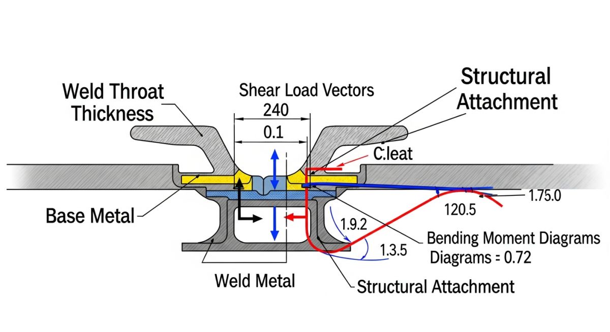
Designing a clip requires a deep understanding of the interaction between the attachment and the shell. The primary concern is the “local stress” induced by the clip. When a load is applied to a clip, it creates a bending moment and a shear force at the weld line. If the shell is thin, this force can cause local buckling or shell deformation.
I always start by calculating the load path. If the clip supports a platform, the load is primarily vertical (dead weight) and horizontal (wind/seismic). We must check the shell stress using the WRC 107/297 methodology or Finite Element Analysis (FEA) for complex geometries. The goal is to keep the combined membrane and bending stress below the allowable stress intensity (Sm) of the shell material.
Field Warning: The “Direct Weld” Trap
Never weld a heavy structural clip directly to a thin-walled pressure vessel shell without a reinforcing pad. The stiffness mismatch between the heavy clip and the thin shell creates a stress concentration factor that often exceeds the fatigue limit of the material. Always use a pad plate of the same material as the shell to transition the stiffness gradually.
When calculating the weld size, we must account for the full load, including dynamic factors. The weld throat (t) is determined by the formula: t = F / (L * 0.707 * S_allow), where F is the applied force, L is the weld length, and S_allow is the allowable shear stress of the weld metal. In my experience, it is safer to use a slightly larger fillet weld than the minimum required, provided it does not cause excessive heat-affected zone (HAZ) embrittlement.
Thermal expansion is another critical factor. If the vessel operates at high temperatures, the clip and the shell will expand at different rates if the materials differ. This differential expansion can induce significant secondary stresses. I recommend using slotted holes in the clip if the attachment is for a sliding support, allowing the vessel to grow without dragging the structural steel with it.
Structural Attachment Performance: A balanced evaluation of the mechanical benefits and potential failure modes associated with integrating fixed clips into high-pressure containment systems.
Advantages
- Provides rigid, permanent support for insulation and fireproofing systems.
- Allows for precise alignment of external piping and instrumentation conduits.
- Enables modular construction by allowing platforms to be pre-fabricated and attached in the field.
- Distributes localized loads effectively when designed with appropriate pad plates.
- Simplifies maintenance by providing secure anchor points for scaffolding and rigging.
Disadvantages
- Creates potential stress risers that can initiate fatigue cracks in the shell.
- Requires extensive NDT (Non-Destructive Testing) to ensure weld integrity.
- Increases the risk of corrosion under insulation (CUI) at the attachment interface.
- Complicates the vessel stress analysis, often requiring complex FEA modeling.
- Differential thermal expansion can lead to shell distortion if not properly accounted for.
Industrial Attachment Integration: The practical deployment of structural clips across diverse process environments to ensure operational stability and regulatory compliance.
Refinery Column Insulation Support
In large-scale distillation columns, clips are used to support heavy mineral wool insulation and aluminum cladding. These clips must be spaced to prevent insulation sagging while minimizing the number of penetrations through the vessel’s weatherproofing barrier.
Platform and Ladder Attachment
Access platforms for maintenance personnel require robust structural clips that can handle both static dead loads and dynamic live loads. These attachments are typically designed with heavy-duty pad plates to ensure the shell can withstand the moment generated by the platform cantilever.
Piping Support and Guide Lugs
Process piping often requires guides or anchors attached directly to the vessel shell to manage thermal expansion of the connected lines. These clips act as hard stops or sliding surfaces, requiring low-friction materials or specialized coatings to prevent galling during operation.
Seismic Restraint Systems
In earthquake-prone regions, vessel clips serve as critical anchor points for seismic bracing. These attachments are engineered to transfer massive lateral forces into the vessel’s foundation, requiring high-strength welding and rigorous post-weld heat treatment (PWHT) verification.
Selecting the appropriate material and geometry for pressure vessel clips requires a rigorous evaluation of the operating environment, specifically focusing on the thermal expansion coefficients and the base metal compatibility. In my experience, engineers often overlook the differential thermal expansion between the vessel shell and the attachment clip, which can induce significant secondary stresses at the weld toe if not properly accounted for in the design phase.
The following table outlines standard material pairings and load-bearing capacities for typical carbon steel and stainless steel vessel applications. These values assume compliance with ASME Section VIII, Division 1, and require verification through finite element analysis (FEA) for non-standard geometries or high-vibration service conditions.
| Clip Type | Material Grade | Max Design Load (kN) | Weld Requirement |
|---|---|---|---|
| Standard Cleat | SA-516 Gr 70 | 15.5 | 6mm Fillet |
| Heavy Duty Lug | SA-240 316L | 45.0 | 8mm Full Pen |
| Insulation Support | SA-36 | 5.2 | 4mm Fillet |
Always ensure that the weld procedure specification (WPS) is qualified for the specific base metal thickness of the vessel shell to prevent underbead cracking or excessive heat-affected zone (HAZ) embrittlement.
The structural integrity of pressure vessel attachments is governed by a complex interplay of geometric constraints, material properties, and regulatory standards. This matrix serves as a quick-reference guide for mapping specific engineering entities to their corresponding design requirements and industry-standard documentation.
By aligning these parameters, designers can ensure that every clip or cleat installed on a pressure boundary meets the stringent safety requirements mandated by global pressure vessel codes. Pay close attention to the “Standard Reference” column, as these documents provide the specific calculation methodologies for stress concentration factors (SCF) and allowable weld stresses.
| Entity | Primary Parameter | Standard Reference |
|---|---|---|
| Vessel Shell | Minimum Design Metal Temp | ASME VIII-1 |
| Attachment Weld | Throat Thickness | AWS D1.1 |
| Clip Geometry | Section Modulus | AISC 360 |
Utilizing this matrix during the preliminary design review helps in identifying potential conflicts between structural requirements and pressure boundary integrity early in the project lifecycle.
Before any structural attachment is finalized on a pressure vessel, a comprehensive site verification process is mandatory. This ensures that the as-built condition matches the design intent and that no unauthorized modifications have compromised the vessel’s pressure-retaining capability. In my experience, the most common failures occur due to improper weld preparation or the use of non-certified materials during field modifications.
-
Material Traceability: Verify that all clip materials match the vessel’s Material Test Reports (MTR) and are compatible with the shell material per ASME Section II. -
Weld Procedure Qualification: Confirm that the welder is qualified for the specific joint configuration and that the WPS is approved for the vessel’s design pressure and temperature. -
Surface Preparation: Ensure the vessel shell surface is free of scale, oil, and moisture within 50mm of the weld zone to prevent porosity. -
Post-Weld Inspection: Perform mandatory NDT (Magnetic Particle or Dye Penetrant) on all attachment welds to detect surface-breaking cracks. -
Clearance Verification: Check that the clip placement does not interfere with nozzle reinforcement pads or existing circumferential weld seams.
Always document the final inspection results in the project’s quality assurance dossier. If any deviation from the approved drawings is identified, a formal Management of Change (MOC) process must be initiated before proceeding with the installation.
Field Case Study: Real-World Application
Problem: Premature Weld Cracking on High-Temperature Vessel
- Thermal cycling caused fatigue at the clip-to-shell interface.
- The clip design lacked a radius, creating a severe stress concentration point.
- Incompatible filler metal was used during a field repair, leading to brittle weld zones.
- The attachment was placed too close to a longitudinal weld seam, violating spacing requirements.
Outcome: Successful Remediation and Design Optimization
- Replaced rigid clips with flexible, radius-edged designs to accommodate thermal expansion.
- Implemented a controlled pre-heat and post-weld heat treatment (PWHT) procedure.
- Verified weld integrity using ultrasonic testing (UT) to ensure full penetration.
- Established a new inspection interval based on the revised stress analysis model.
My recommendation for similar high-temperature applications is to always prioritize the use of “soft” attachment designs that allow for controlled movement, thereby reducing the stress intensity at the weld toe.
Frequently Asked Engineering Questions
What is the minimum distance between vessel clips and shell welds?
Maintaining adequate clearance between attachments and pressure-retaining welds is critical to avoid overlapping heat-affected zones. My standard practice follows these guidelines:
- Maintain a minimum of 50mm or 4 times the shell thickness, whichever is greater, from any longitudinal or circumferential weld.
- This prevents the interaction of residual stresses from the attachment weld and the primary pressure boundary weld.
- Always consult the specific project specification, as some high-pressure services require even larger clearance buffers.
How do I calculate the stress concentration factor for a clip?
Calculating the stress concentration factor (SCF) for a vessel clip involves evaluating the geometric discontinuity at the weld toe. I recommend the following approach:
- Utilize empirical formulas found in WRC Bulletin 107 or 297 for local stress analysis.
- For complex geometries, perform a 3D finite element analysis (FEA) to determine the peak stress at the attachment point.
- Ensure the calculated local stress, when combined with primary membrane stresses, does not exceed the allowable limits defined in ASME Section VIII, Division 2.
Are full penetration welds required for all vessel clips?
Not all clips require full penetration welds; the weld type is dictated by the load and the service environment. Consider these factors:
- Fillet welds are generally sufficient for light-duty attachments like insulation supports or small piping clips.
- Full penetration welds are mandatory for structural supports that carry significant dead loads or dynamic forces.
- Always verify the weld size against the shear and bending moment requirements of the specific attachment.
What is the impact of PWHT on attachment welds?
Post-Weld Heat Treatment (PWHT) is essential for relieving residual stresses in the heat-affected zone of attachment welds. My experience highlights these key points:
- PWHT reduces the risk of stress corrosion cracking in sensitive materials like carbon steel or chrome-moly alloys.
- Ensure the heating and cooling rates are strictly controlled to prevent thermal shock to the vessel shell.
- Verify that the attachment material is compatible with the PWHT cycle to avoid degradation of mechanical properties.
How do I handle clips on lined or clad vessels?
Attaching clips to lined or clad vessels requires extreme caution to avoid damaging the corrosion-resistant layer. Follow these technical steps:
- Avoid welding directly to the cladding if possible; use a backing pad or a specialized attachment design.
- If welding to the cladding is unavoidable, ensure the weld procedure is qualified for the specific cladding material.
- Perform a leak test or NDT on the cladding integrity after the attachment is completed to ensure no contamination of the base metal.
What documentation is required for vessel clip installation?
Proper documentation is the backbone of pressure vessel safety and regulatory compliance. You must maintain the following records:
- Certified Material Test Reports (CMTR) for all clip components.
- Approved Weld Procedure Specifications (WPS) and Procedure Qualification Records (PQR).
- Welder Performance Qualification (WPQ) records for the specific personnel involved.
- NDT reports confirming the absence of defects in the attachment welds.
📚 Recommended Resources: Pressure Vessel Clips

Complete Course on
Piping Engineering
Check Now
Key Features
- 125+ Hours Content
- 500+ Recorded Lectures
- 20+ Years Exp.
- Lifetime Access
Coverage
- Codes & Standards
- Layouts & Design
- Material Eng.
- Stress Analysis
