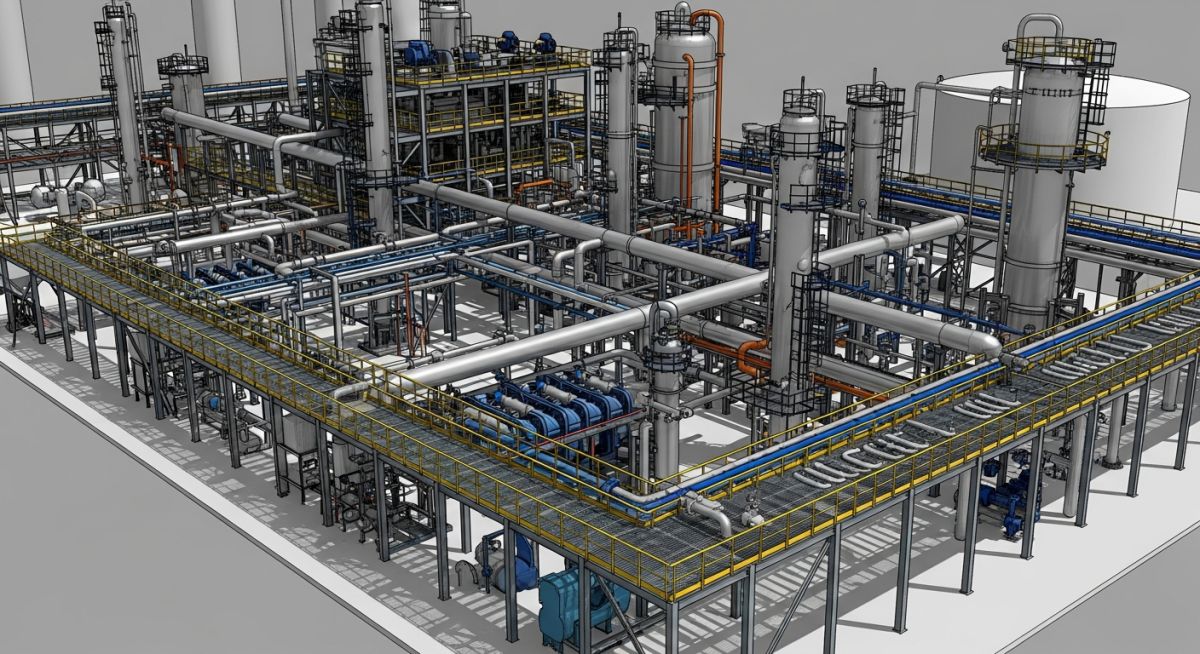
A Guide to Plant Clearances and Access Requirements
In my 20-plus years of piping engineering, I have seen beautiful 3D CAD models that looked like works of art on a screen, only to become operational nightmares in the field. I remember a specific sulfur recovery unit where a designer routed a massive 14-inch high-pressure steam header directly in front of a shell-and-tube heat exchanger’s channel head. When the first turnaround arrived, the maintenance crew realized they could not pull the tube bundle without cutting out a section of the live steam line. That single oversight cost the operator three days of unscheduled downtime and hundreds of thousands of dollars.
This guide draws on those hard-earned field lessons to establish a definitive framework for industrial spatial design. We will explore how to balance the competing demands of structural steel, piping systems, and heavy equipment to create a plant layout that is safe to operate and highly efficient to maintain.
Key Takeaways
- Establish clear maintenance envelopes early in the 3D modeling phase to prevent costly field modifications.
- Adhere strictly to OSHA and NFPA standards for egress pathways to guarantee operator safety during emergencies.
- Integrate rigging and crane access requirements directly into the equipment layout design.
Mastering Plant Clearances and Access Requirements
Designing an industrial facility requires a deep understanding of how human operators and maintenance machinery interact with physical hardware. We must design not just for the plant’s normal operating state, but for its most chaotic moments: emergency shutdowns and major turnarounds. This requires a rigorous application of codes from organizations like the American Society of Mechanical Engineers (ASME) and the Occupational Safety and Health Administration (OSHA).
The Physics of Maintenance Envelopes
To calculate the minimum clearance required for pulling a heat exchanger tube bundle, we must account for several variables. Let Lb represent the physical length of the tube bundle. Let Lr represent the rigging clearance required for the crane hook and slings, which is typically a minimum of 1500 millimeters. Let Cs represent the safety margin to clear adjacent piping or structural columns, which must be at least 500 millimeters.
The total clearance length (Lc) measured from the face of the channel flange is calculated as follows:
For a standard 6000 millimeter tube bundle, this requires a completely unobstructed horizontal corridor of 8000 millimeters. If this corridor is compromised by structural bracing or small-bore piping, the maintenance crew will be forced to perform complex, high-risk rigging maneuvers, or worse, cut structural members during a turnaround.
Pump and Compressor Access Zones
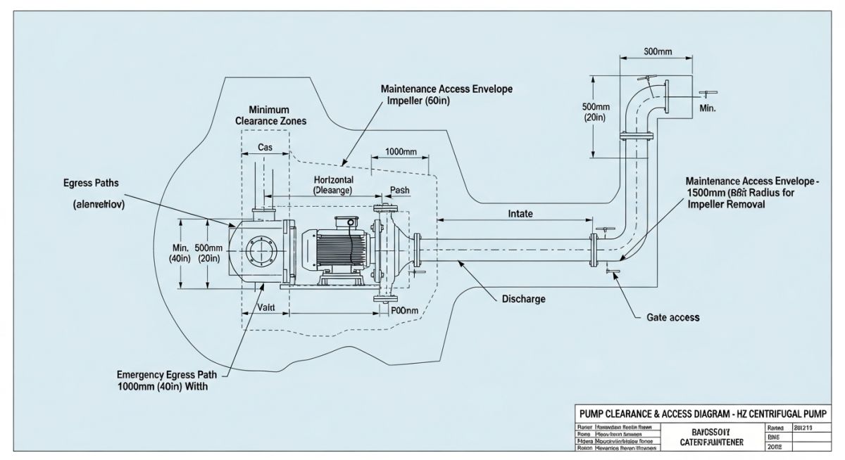
For horizontal centrifugal pumps, the spacing between adjacent pumps must allow for the removal of the motor and the pump casing cover. In my experience, a minimum clear space of 1000 millimeters between the outer edges of adjacent pump bases is necessary. This space allows maintenance technicians to position portable gantry cranes, A-frames, or utility carts.
Furthermore, the suction and discharge piping must be routed such that they do not block access to the pump’s coupling or bearing housing. Mechanical seals are high-maintenance components; if a technician cannot easily access the seal chamber with standard tools, seal replacement times will double, directly impacting plant availability.
Never route small-bore piping, electrical conduits, or instrument cable trays within the designated bundle pull or pump maintenance envelopes. These systems are frequently damaged during turnarounds when heavy rigging equipment is deployed, leading to costly repairs and start-up delays.
Standardizing Plant Clearances and Access Requirements
The following table outlines the standard clearance dimensions that I have utilized across dozens of successful petrochemical and refining projects. These dimensions represent a synthesis of international codes and practical field experience.
| Equipment Type | Minimum Horizontal Clearance | Minimum Vertical Clearance | Primary Code Reference |
|---|---|---|---|
| Pumps (Centrifugal) | 1000 mm between pump bases | 2100 mm headroom | ASME B31.3 |
| Heat Exchangers | Bundle length + 1500 mm | 2100 mm headroom | ASME Section VIII |
| Compressors (Reciprocating) | 1500 mm around maintenance points | 3000 mm overhead crane clearance | API 618 |
| Vessels & Columns | 1000 mm around manways | 2100 mm above platforms | OSHA 1910.36 |
| Main Walkways | 1200 mm clear width | 2300 mm headroom | OSHA 1910.37 |
To ensure complete alignment across engineering disciplines, this matrix maps core technical entities and physical parameters to their respective design standards.
| Entity / Acronym | Technical Definition | Design Parameter | Standard Reference |
|---|---|---|---|
| NPSH | Net Positive Suction Head | Pump suction piping layout and elevation | API 610 |
| Bundle Pull | Space required to extract heat exchanger tubes | Bundle length + rigging allowance | ASME Section VIII |
| Egress Path | Continuous and unobstructed path of travel | Minimum 710 mm width | NFPA 101 |
| Headroom | Vertical clearance above walking surfaces | Minimum 2300 mm for exit routes | OSHA 1910.37 |
| Maintenance Envelope | Dedicated space for tool clearance and component removal | Equipment footprint + 1000 mm | Industry Best Practice |
How to Verify Site Clearance Compliance
Before signing off on any plant layout or piping design, I insist on a rigorous physical or virtual walkthrough. Use this checklist during model reviews and field inspections to guarantee compliance with safety and maintenance standards.
Field Clearance Audit Checklist
-
Egress Pathways: Verify that all primary and secondary egress paths meet the minimum width of 710 mm per NFPA 101 and are completely free of obstructions.
-
Exchanger Bundle Pulls: Confirm that heat exchanger bundle pull areas are completely free of piping, structural steel, and electrical trays.
-
Pump Maintenance Envelopes: Check that pump maintenance envelopes allow for motor removal without disturbing adjacent piping or structural columns.
-
Valve Accessibility: Ensure all valves requiring manual operation are positioned between 500 mm and 1800 mm above the walking surface.
-
Vertical Headroom: Validate that vertical headroom along all walkways is at least 2100 mm, and 2300 mm along designated exit routes.
Field Case Study: Real-World Application
The Problem: The Blocked Bundle Pull
During a scheduled turnaround at a Gulf Coast petrochemical facility, the maintenance team attempted to pull the tube bundle of a high-pressure feed preheater. However, a newly installed structural support column for an overhead pipe rack blocked the bundle’s path by 300 millimeters. The 3D model had not been updated with the as-built structural modifications, leading to a major clash. The turnaround schedule was delayed by 48 hours while engineers designed a temporary structural shoring system to allow the removal of the blocking column.
The Outcome: Resolution and Prevention
The temporary shoring system was successfully installed, allowing the column to be unbolted and the bundle to be pulled. The total cost of the delay, including emergency engineering services and extended crane rentals, exceeded 180,000. To prevent future occurrences, the facility implemented a mandatory 3D laser scanning protocol for all brownfield modifications, ensuring that the digital twin matches the physical reality before any turnaround planning begins.
My direct recommendation for any brownfield project is to never rely solely on legacy 2D drawings. Always perform a 3D laser scan of the area to capture as-built clearances before finalizing your piping and equipment layouts.
Frequently Asked Engineering Questions
What is the minimum width for an industrial egress pathway?
How do thermal expansion movements affect piping clearances?
What are the clearance requirements for control valve stations?
Can electrical cable trays run through equipment maintenance envelopes?
How is the clearance for crane access determined in a plant layout?
What is the standard height for operating valve handwheels?
Complete Course on
Piping Engineering
Check Now
Key Features
- 125+ Hours Content
- 500+ Recorded Lectures
- 20+ Years Exp.
- Lifetime Access
Coverage
- Codes & Standards
- Layouts & Design
- Material Eng.
- Stress Analysis