Table of Contents
What Causes Piping System Stresses in Industrial Plants?
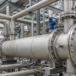
In my 20 years of managing piping stress analysis for high-pressure petrochemical plants, I have seen how minor design oversights lead to catastrophic field failures. Piping systems are not static conduits; they are dynamic, flexible structures that expand, contract, vibrate, and sustain heavy loads. When we design a piping system, we are constantly balancing the need for structural support with the necessity of flexibility. Understanding what causes these stresses is the first step toward engineering a safe, reliable, and code-compliant facility.
Every pipe run is subjected to a complex matrix of forces. Some of these forces are constant, such as the weight of the pipe and the fluid it carries. Others are transient, like the sudden pressure surge of a water hammer or the cyclic thermal expansion as a process line heats up to 400 degrees Celsius. If these forces are not properly routed to the structural steel via engineered supports, they will find the weakest point in your system—usually a costly compressor nozzle, a fragile valve body, or a critical flange connection.
Key Takeaways for Piping Engineers
- Primary stresses are non-self-limiting and can cause catastrophic plastic collapse if they exceed the material yield strength.
- Secondary stresses are self-limiting and are driven by thermal expansion or displacement, which can be mitigated through piping flexibility.
- Proper support selection, such as variable spring hangers and guides, is critical to balancing sustained and thermal loads.
To understand how stresses develop, we must first categorize them according to their behavior and limits. Under the ASME B31.3 Process Piping code, stresses are split into primary, secondary, and occasional categories. Each category has a distinct physical mechanism and a different allowable limit.
Primary Stresses: The Silent Killers
Primary stresses are developed by external mechanical loads and are non-self-limiting. This means that if the load exceeds the yield strength of the material, the pipe will continue to deform until it ruptures or collapses. The most common primary stresses are hoop stress and longitudinal stress caused by internal pressure, as well as bending stresses caused by the deadweight of the pipe, insulation, and process fluid.
The hoop stress (Sh) in a thin-walled cylinder is calculated using the classic Barlow’s formula:
Where P is the internal design pressure, D is the outside diameter of the pipe, and t is the nominal wall thickness minus corrosion allowance. If this stress exceeds the allowable stress limit of the material at design temperature, ductile failure is inevitable.
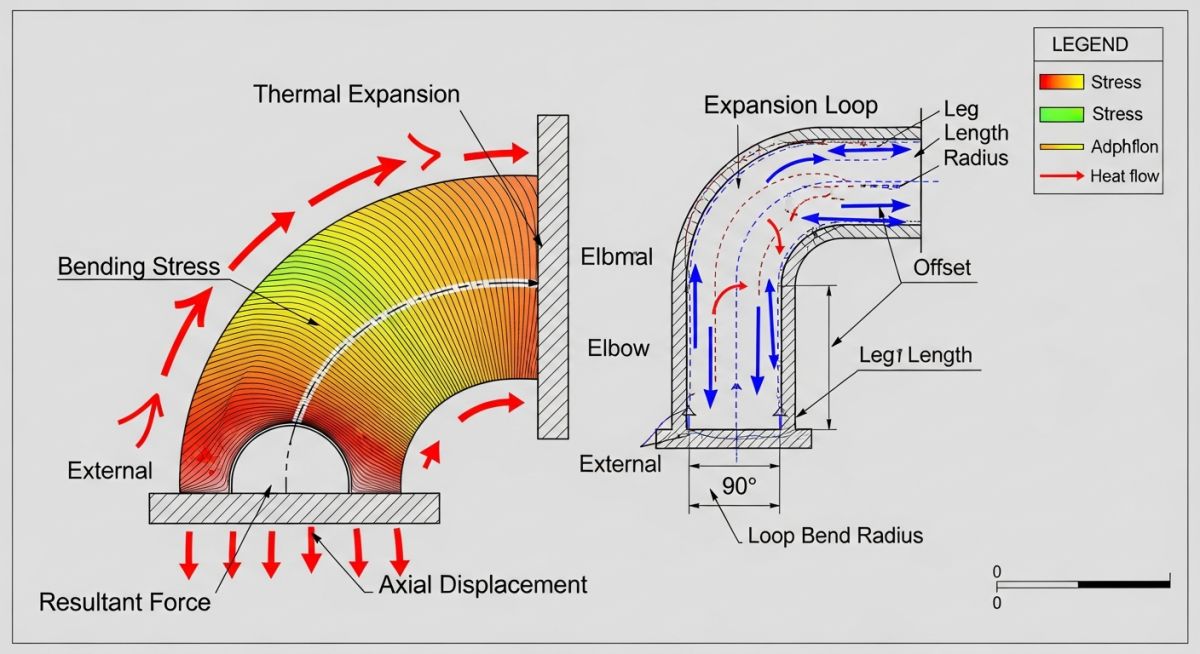
Secondary Stresses: Thermal Expansion and Flexibility
Unlike primary stresses, secondary stresses are self-limiting. They are caused by displacement rather than external loads. The most common cause is thermal expansion. When a pipe heats up, it expands according to its coefficient of thermal expansion. If this expansion is restricted by rigid anchors, the pipe experiences compressive stress.
The thermal expansion displacement (Delta L) is calculated as:
Where L is the length of the pipe run, alpha is the mean coefficient of thermal expansion, and Delta T is the difference between the operating and ambient temperatures. If the piping layout is too stiff, this expansion generates massive forces at the anchor points, leading to high bending stresses.
To design a safe piping system, we must analyze all potential load cases. These loads are generally divided into sustained loads (which are always present) and occasional loads (which occur during specific environmental or operational events).
Sustained Loads: Weight and Pressure
Sustained loads are the baseline forces that the piping system must support throughout its operating life. They include:
- Pipe Deadweight: The bare weight of the steel pipe, fittings, flanges, and inline valves.
- Insulation and Cladding: Heavy insulation materials like calcium silicate or cellular glass, along with aluminum or stainless steel cladding.
- Fluid Weight: The weight of the process fluid during operation, or the weight of water during hydrostatic testing (which is often much heavier than the operating fluid).
- Internal Pressure: The radial and axial forces exerted by the pressurized fluid on the pipe wall.
Occasional Loads: Environmental and Dynamic Forces
Occasional loads are transient events that can introduce massive dynamic forces into the system. These must be analyzed in compliance with ASME B31.1 Power Piping or ASME B31.3 depending on the facility type. They include:
- Wind Loads: External wind pressure acting on outdoor, elevated piping runs, especially on tall columns or pipe racks.
- Seismic Loads: Ground acceleration during an earthquake, which requires the installation of seismic snubbers or restraints.
- Water Hammer (Fluid Transients): The rapid pressure surge caused by the sudden closure of a valve or the startup of a pump, which can tear piping off its supports.
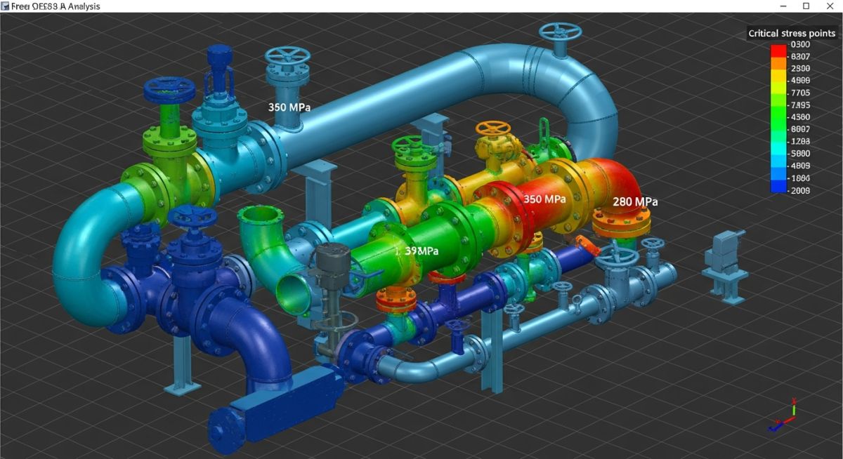
As piping engineers, we must ensure that the calculated stresses in our piping systems do not exceed the allowable limits defined by the applicable design codes. The table below outlines the primary stress categories, their load types, and the corresponding code limits per ASME B31.3.
| Stress Category | Load Type | ASME B31.3 Code Limit | Typical Mitigation Method |
|---|---|---|---|
| Sustained (SL) | Internal Pressure + Deadweight | Sh (Allowable stress at design temp) | Add structural supports, optimize hanger spacing |
| Displacement (SE) | Thermal Expansion + Displacement | SA (Allowable displacement stress range) | Add expansion loops, offsets, or expansion joints |
| Occasional (SO) | Wind, Seismic, Relief Valve Thrust | 1.33 * Sh (or code-specified multiplier) | Install wind guides, seismic snubbers, sway braces |
To perform a rigorous stress analysis, we must map various physical parameters and structural acronyms to their corresponding design standards and engineering impacts.
| Acronym / Entity | Physical Parameter | Applicable Code / Standard | Design Impact & Significance |
|---|---|---|---|
| SIF | Stress Intensification Factor | ASME B31.3 Appendix D / ASME B31J | Quantifies localized stress concentration at tees, elbows, and branch connections. |
| WRC 107/297 | Local Nozzle Stresses | Welding Research Council Bulletins | Evaluates local stresses on vessel walls and equipment nozzles from piping loads. |
| API 610 | Pump Nozzle Loads | API Standard 610 | Defines maximum allowable forces and moments on centrifugal pump nozzles. |
| API 617 | Compressor Nozzle Loads | API Standard 617 | Strict limits on centrifugal compressor nozzles to prevent shaft misalignment. |
Even the most sophisticated 3D stress analysis model is useless if the field installation does not match the design. During my site audits, I frequently find supports installed in the wrong locations, spring hangers with travel stops still inserted, or rigid supports where guide supports were specified. Use this checklist to verify your piping system’s stress profile on site.
Field Stress Verification Checklist
-
Spring Hanger Travel Stops: Verify that all shipping and travel stops have been removed from variable and constant spring hangers after hydrostatic testing and before commissioning.
-
Support Clearances: Ensure that guide supports and line stops have the specified clearances (typically 1.5mm to 3mm) to allow axial movement while preventing lateral buckling.
-
Flange Alignment: Check that flange faces are parallel and concentric before bolt-up to prevent excessive assembly stresses on equipment nozzles.
-
Expansion Joint Tie Rods: Confirm that expansion joint shipping bars are removed and that tie rods are adjusted to their correct operating lengths.
-
Structural Steel Integrity: Inspect the structural steel members supporting heavy anchors to ensure there is no visible deflection or weld cracking under operating loads.
Field Case Study: Real-World Application
The Problem: Chronic Flange Leakage and Nozzle Overload
At a major petrochemical facility, a 12-inch high-pressure steam line operating at 380°C was experiencing chronic flange leakage at the inlet nozzle of a critical steam turbine. The turbine manufacturer reported that the nozzle loads exceeded the allowable limits specified in NEMA SM-23 by over 200%. The plant was facing frequent unscheduled shutdowns, costing upwards of 150,000 per day in lost production.
The Solution: Flexibility Redesign and Support Optimization
I was called in to perform a comprehensive stress analysis using CAESAR II. Our investigation revealed that the piping run was extremely stiff, with a rigid anchor placed too close to the turbine nozzle. We redesigned the piping layout by adding a 3D expansion loop to absorb the thermal growth. Additionally, we replaced two rigid supports near the turbine with variable spring hangers to allow vertical movement while supporting the deadweight.
By introducing the expansion loop and optimizing the support configuration, we reduced the bending moments on the turbine nozzle by 78%, bringing them well within NEMA SM-23 limits. The flange leakage was completely resolved, and the system has operated continuously without a single failure for over five years.
Frequently Asked Engineering Questions
What is the difference between primary and secondary stress?
How does water hammer cause piping system stresses?
Why is ASME B31.3 used instead of ASME B31.1 for process plants?
How do spring hangers mitigate thermal expansion stresses?
What is a stress intensification factor (SIF)?
How does soil settlement affect buried pipeline stresses?
Complete Course on
Piping Engineering
Check Now
Key Features
- 125+ Hours Content
- 500+ Recorded Lectures
- 20+ Years Exp.
- Lifetime Access
Coverage
- Codes & Standards
- Layouts & Design
- Material Eng.
- Stress Analysis

📚 Recommended Resources: piping system stresses
Read these Guides
🎓 Advanced Training


Related posts:
![Super duplex stainless steel piping network on an offshore oil drilling platform.]()
Super Duplex Stainless Steel Oil and Gas Piping Design Guide
![Industrial duplex stainless steel piping system in a chemical processing facility.]()
Understanding Duplex Stainless Steel Properties and Industrial Piping Applications
![A welder performing a critical golden joint weld on an industrial steel pipeline.]()
What is a Golden Joint in Piping Systems?
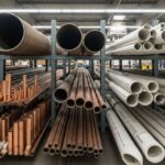
![A collection of different types of industrial pipes classified by material and size on a storage rack.]()
Comprehensive Guide to Types of Pipes and Industrial Classification Systems
![Industrial piping network with digital overlays representing inch-dia and inch-meter engineering calculations.]()
What are Inch-Dia and Inch-Meter in Piping Systems?
![Industrial piping system featuring a large U-shaped pipe expansion loop on an elevated rack.]()
How to Design Pipe Expansion Loops for Piping Systems