Piping Isometric Drawing: The Engineer’s Guide to Symbols & Offsets
A Piping Isometric Drawing (often called an “Iso”) is the primary communication tool between the piping design engineer and the construction team. Unlike orthographic plans (Top/Side views), an Iso represents a 3D piping system on a 2D sheet of paper by rotating the object 45 degrees and tilting it 35.26 degrees, allowing vertical and horizontal pipes to be drawn to scale on a single plane.
What is a Piping Isometric?
It is a “Not-to-Scale” schematic used for fabrication and stress analysis. While the pipe lengths are dimensioned accurately, the drawing lines themselves are not visually scaled. Key features include the North Arrow Orientation, the Bill of Materials (BOM), and specific Weld Symbols that dictate where the pipe is cut and welded.
Quick Navigation
🧠 Test Your Isometric IQ
Loading…
Complete Course on
Piping Engineering
Check Now
Key Features
- 125+ Hours Content
- 500+ Recorded Lectures
- 20+ Years Exp.
- Lifetime Access
Coverage
- Codes & Standards
- Layouts & Design
- Material Eng.
- Stress Analysis
The Geometry of a Piping Isometric Drawing
The fundamental challenge in industrial construction is translating a three-dimensional reality into a two-dimensional plan. A standard orthographic view (Top/Front) fails to show vertical changes clearly. The Piping Isometric Drawing solves this by using a specific projection method where the three spatial axes (x, y, z) are equally foreshortened.
In this system, vertical lines stay vertical, but horizontal lines are drawn at 30° angles to the horizon. To read a Piping Isometric Drawing correctly, you must first locate the North Arrow Orientation. Typically located in the top-left corner, this arrow aligns the drawing “Plant North” with the actual site coordinates. Without this check, a spool manufactured perfectly to dimensions could be installed facing the wrong direction.
Mastering the Piping Isometric Symbols Legend
Every line on the paper represents the pipe centerline. However, the dots, crosses, and squiggles tell the fabricator exactly how to join the pipes. Consulting the Piping Isometric Symbols Legend is mandatory for every project, as specific client standards (e.g., Shell vs. Exxon) may vary slightly.
Field Weld vs. Shop Weld: The Critical Distinction
One of the most expensive mistakes in construction is confusing a Field Weld vs Shop Weld.
- Shop Weld (SW): Usually represented by a solid black dot. These joints are welded in a controlled workshop environment to create a “Spool.”
- Field Weld (FW): Usually represented by an ‘X’ or an open circle. These connect two separate spools at the construction site.
- Field Fit Weld (FFW): Represented by an ‘X’ with extra text (e.g., “F.F.”). This indicates the pipe has been left 6-8 inches longer (Field Allowance) to be measured, cut, and welded in position to account for site deviations.

| Symbol Type | Visual Representation | Function & Meaning |
|---|---|---|
| Shop Weld (SW) | Solid Black Dot (●) | Permanent joint welded in the fab shop. Defines the boundary of a single spool. |
| Field Weld (FW) | Cross (X) or Open Circle (○) | Joint welded at the site rack. Connects two pre-fabricated spools. |
| Flange (FLG) | Two parallel vertical lines (||) | Bolted connection. Used for valves, equipment nozzles, or removable spools. |
| Flow Arrow | Arrow on line (→) | Indicates fluid direction. Critical for Check Valves and Strainer installation. |
| Slope Symbol | Small Triangle with Ratio | Indicates gravity flow. E.g., “1:100” means 1 unit drop for every 100 units length. |
The Rolling Offset Calculation
Often, a pipe cannot run in a straight line due to an obstruction (like a steel column or cable tray). It must “roll” around the obstacle, changing elevation and horizontal position simultaneously. This is drawn as a hatched triangle on the Piping Isometric Drawing.
To fabricate this, the pipe fitter needs the “Travel” length—the actual length of the diagonal pipe piece. This is a classic Rolling Offset Calculation based on the Pythagorean theorem.
💡 Engineering Formula: Rolling Offset Travel
The pipe forms a 3D box. We usually have the Set (Vertical change) and the Run (Horizontal change).
Travel² = Set² + Run²
Travel = √( Set² + Run² )
*Note: If the roll is “Double Rolling” (changing X, Y, and Z simultaneously), the formula expands to: Travel = √( X² + Y² + Z² )
From Iso to Fabrication
Once the geometry is defined, the data is extracted into Spool Fabrication Drawings. These are individual sheets for every shop-welded segment. The Iso acts as the master map, while the spool drawings are the puzzle pieces.
Finally, accurate material procurement relies on the Piping Bill of Materials (BOM) located on the right side of the Iso. This list connects every item number on the drawing (e.g., balloon #4) to a specific material code (e.g., ASTM A106 Gr. B), ensuring that high-pressure lines aren’t accidentally built with standard plumbing pipe.
Case Study: The $50,000 “Field Weld” Error
Project Context
- Facility: Brownfield Refinery Expansion
- System: 10″ Boiler Feed Water (High Pressure)
- Drawing Ref: ISO-BFW-2001-04
Error Impact
- Delay: 3 Days (Critical Path)
- Cost: Crane hold time + Rework crew
- Root Cause: Symbol Interpretation
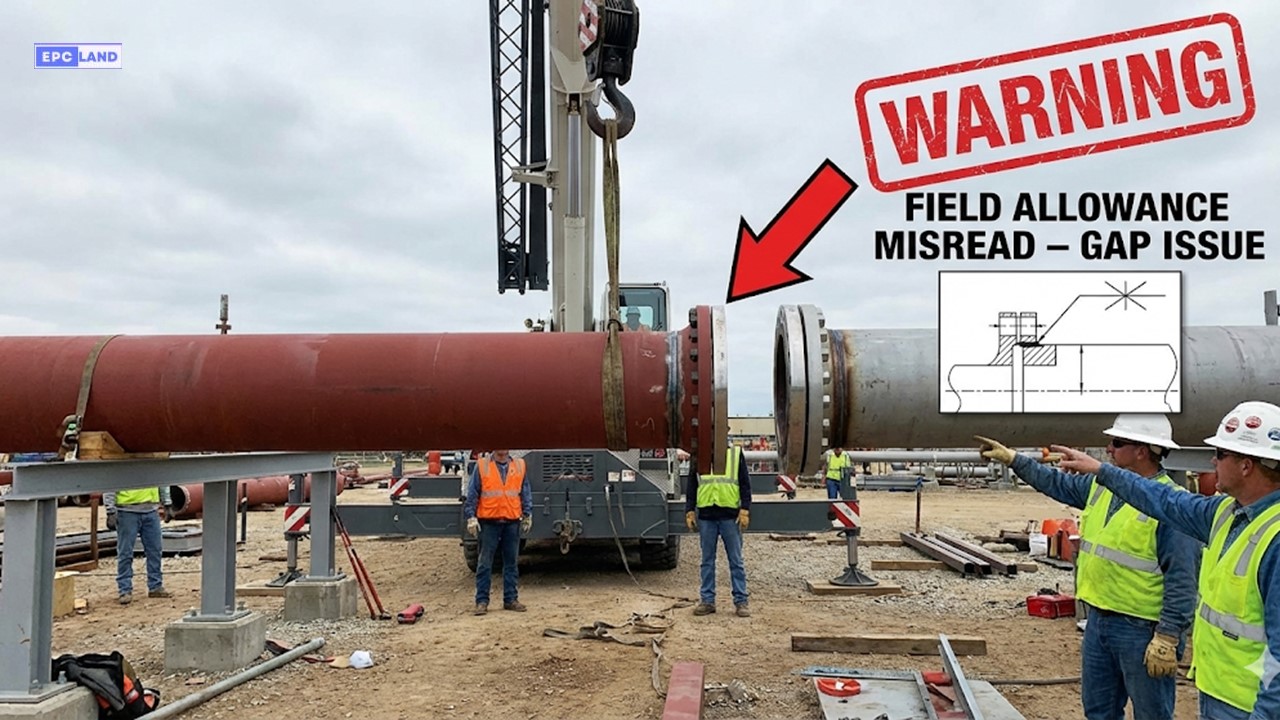
The Incident: A Spool That Was “Perfectly” Wrong
During the tie-in phase of a refinery shutdown, the piping crew attempted to install a new pre-fabricated spool between an existing pump nozzle and a pipe rack flange. The Piping Isometric Drawing clearly showed a total distance of 3,500mm.
The fabrication shop built the spool exactly to 3,500mm. However, when the riggers lifted the spool into place, it was short by 50mm, making the connection impossible without stressing the pump nozzle. Work was immediately halted.
Root Cause Analysis
The error was traced back to a misinterpretation of the Piping Isometric Symbols Legend during the generation of the Spool Fabrication Drawings.
- The Symbol: The Iso marked the final joint with an ‘X’ symbol labeled “F.F.” (Field Fit).
- The Meaning: A Field Fit weld requires the fabricator to leave an extra 100-150mm of pipe (“Field Allowance”) beyond the theoretical dimension. This allows the field crew to measure the actual distance at the site, cut the pipe to the precise size, and weld it.
- The Mistake: The shop floor treated it as a standard Shop Weld (SW) or a pre-cut Field Weld (FW) and cut the pipe to the exact theoretical length shown on the dimension line. Because the existing pump foundation had settled slightly over 20 years, the theoretical dimension was wrong.
The Field Fix & Lesson
Since the spool was too short, it could not be stretched. The solution involved:
- Cutting the newly painted spool.
- Welding in a “pup piece” (a short extension section) to bridge the gap.
- Performing unplanned Radiography (RT) on the two new butt welds.
- Re-hydrotesting the line segment.
🚧 Engineering Takeaway
Never trust theoretical dimensions for tie-ins. Always verify if the Field Weld vs Shop Weld designation includes “Field Fit” (F.F.) allowance. If the Iso shows F.F., the pipe MUST leave the shop long. A spool that is long can be cut; a spool that is short is scrap.
Piping Isometric Drawings vs. Orthographic Drawings
In engineering design, both document types are essential, but they serve different phases of the project. While Orthographic drawings (General Arrangement Drawings or GADs) place the pipe in the context of the whole plant, Piping Isometric Drawings isolate the line for fabrication.
| Feature | Orthographic Drawings (GADs) | Piping Isometric Drawings |
|---|---|---|
| Perspective | Single Plane (Top, Front, or Side View). | 3D Perspective (X, Y, Z axes visible). |
| Scale | Drawn “To Scale” (e.g., 1:50). | Not to Scale (Schematic representation). |
| Complexity | Requires multiple drawings to see full route. | Shows entire complex route in one view. |
| Primary Use | Plant Layout, Clash Detection, Civil work. | Fabrication, Stress Analysis, Material Takeoff. |
Uses Across the Project Lifecycle
Beyond basic construction, Piping Isometric Drawings act as the “Bible” for the piping system throughout the facility’s life.
Fabrication & Construction
Fabricators use the specific cut lengths to assemble spools. Site teams use the orientation to weld spools correctly in the rack, reducing fit-up errors.
Design & Analysis
Stress Engineers use Isos to identify support locations and thermal expansion loops. They ensure all components meet pressure specifications.
Maintenance & Retrofits
Years later, maintenance teams use Isos to locate specific welds for inspection or to plan modifications (tie-ins) without shutting down the whole plant.
Dimensions & Creation Workflow
Understanding Dimensions
Because the drawing is not to scale, the written dimensions are the absolute authority.
- Straight Pipe: Always measured Centerline-to-Centerline (C-L to C-L).
- Fittings (Elbows/Tees): Measured from Face-to-Centerline.
- Elevation (EL): Indicates the vertical height relative to the plant datum (Sea Level or Grade).
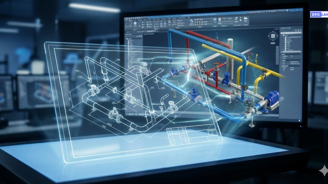
How to Create Piping Isometric Drawings
While modern projects use software like AutoCAD Plant 3D or PDMS to auto-generate Isos, the logic remains the same:
-
1
Gather Inputs
Start with the P&ID (for logic) and the GAD (for routing) to understand the line’s path.
-
2
Draw Centerlines
Sketch the pipe route using the 30-degree isometric axes. Do not worry about length scaling yet.
-
3
Add Components
Insert standard symbols for Valves, Flanges, and Fittings at the correct locations.
-
4
Dimension & Annotate
Add the exact dimensions, tag numbers, and elevation markers. Double-check North Arrow Orientation.
Common Challenges
Errors often arise from Interpretation Mistakes (confusing symbols) or Complexity (cluttered drawings for large lines). Since Isos are Not Scaled, a tiny line on paper could represent 20 meters of pipe, leading to oversight if dimensions aren’t checked rigorously.
EPCLand YouTube Channel
2,500+ Videos • Daily Updates
Essential Piping Calculations & Estimations
A Piping Isometric Drawing is not just a visual guide; it is the primary data source for project controls. Engineers and Quantity Surveyors extract data from Isos to perform critical calculations for procurement, scheduling, and heavy lifting logistics.
Inch-Meter Calculation
Used to estimate the total volume of piping work. It combines the length of the run with the complexity of the diameter.
Inch-Meter = Length (m) × Pipe Size (in)
Example: 10 meters of 6″ pipe = 60 Inch-Meters.
Inch-Dia Calculation
Used specifically to estimate welding labor. A single 24″ joint takes significantly longer than a 2″ joint.
Inch-Dia = Pipe Size (in) × No. of Joints
Example: Two welds on a 10″ pipe = 20 Inch-Dia.
Engineering Physics Calculations
Pipe Weight Calculation
Critical for designing pipe supports and crane lift plans. This formula approximates the mass of the steel cylinder.
- OD: Outer Diameter of pipe.
- Density: For Carbon Steel, use approx. 7.85 g/cm³ (or 7850 kg/m³).
Water Volume for Hydro Testing
Engineers must calculate the volume of water required to fill the system for pressure testing to ensure the structural steel supports can handle the “Wet Weight.”
*Note: Remember to use the Inner Diameter (ID), not the OD.
Insulation Area Calculation
Required for ordering cladding material (Aluminum/SS) to prevent heat loss. This calculates the surface area of the outer jacketing.
*Note: “2 × Thickness” is added because insulation covers both sides of the diameter.
Frequently Asked Questions (FAQ)
What is the difference between a P&ID and a Piping Isometric?
A P&ID (Piping and Instrumentation Diagram) is a schematic showing the logical flow of the process, including control loops and equipment connections, but it is not to scale and has no geographical accuracy. A Piping Isometric Drawing is a physical representation of a specific line, showing exact dimensions, elevations, Rolling Offsets, and material counts required for fabrication.
How do I identify a “Rolling Offset” on the drawing?
Look for a hatched (shaded) triangle along the pipe run. This triangle indicates the pipe is moving in two planes simultaneously (e.g., going Up and East at the same time). The drawing will usually label the vertical leg (Set) and the horizontal leg (Run). You must perform a Rolling Offset Calculation to find the true length (Travel) of that pipe piece.
Why is the North Arrow Orientation sometimes diagonal?
The North Arrow Orientation on the Iso refers to “Plant North,” which is a coordinate system aligned with the facility’s main structures, not necessarily magnetic geographic North. If the arrow points diagonally (e.g., top-right), it means the plant’s main axis is rotated relative to the drawing sheet to maximize space or clarity. Always orient yourself to Plant North before starting fabrication.
Where do I find the material grade for a specific pipe section?
You must reference the Piping Bill of Materials (BOM), typically located in the right-hand column or bottom of the sheet. Find the “Item Number” in a balloon on the drawing (e.g., ‘1’), then look up ‘1’ in the BOM to see the description (e.g., “PIPE, 6 IN, SCH 40, ASTM A106 GR B”). Never guess material based on appearance.
Conclusion: The Language of Piping
The Piping Isometric Drawing is more than just a sketch; it is the contract between design intent and mechanical reality. Mastering this document requires a blend of spatial visualization, mathematical precision for Rolling Offset Calculations, and a strict adherence to the Symbols Legend.
As demonstrated in our case study, a single misinterpretation of a Field Weld vs Shop Weld symbol can cost thousands in rework. Whether you are a drafter generating Spool Fabrication Drawings or a fitter on the rack, your ability to read the “Iso” is the foundation of a safe, leak-free facility.

Related posts:
![Infographic flowchart of the GRP GRE FRP piping stress analysis workflow in START-PROF.]()
Rigid Struts: Definition, Applications, and Modeling in Caesar II
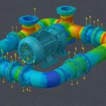
![3D stress analysis model of GRP piping system in START-PROF software showing stress distribution.]()
Stress Analysis of GRP / GRE / FRP Piping using START-PROF
![Industrial centrifugal pump installed on a concrete foundation with precision piping and alignment.]()
How to Use a Pump Installation Checklist for Maximum Reliability
![3D Caesar II pipe stress analysis model of a centrifugal pump piping system showing stress distribution.]()
Pump-Piping Alignment Caesar II Stress Analysis Methodology
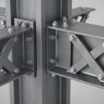
![3D render of a structural steel cross-bracing connection with a gusset plate.]()
Mastering Steel Connections with a Cross-Bracing Design Example
![Industrial engineer checking shaft alignment on a centrifugal pump during commissioning.]()
How to Use a Pump Commissioning Checklist for Start-Up