Pipe Support Brackets: Types, Installation, and Engineering Best Practices
In my 20-plus years of managing piping stress analysis and field installations, I have seen minor support oversights lead to catastrophic plant shutdowns. Pipe support brackets are not mere pieces of bent metal; they are the unsung heroes of industrial piping systems. They maintain structural integrity, control vibration, and ensure that thermal expansion does not turn a high-pressure line into a safety hazard.
When designing or installing these components, we must look beyond the static weight of the pipe. We must account for fluid transients, thermal movements, and environmental loads. This guide draws directly from my field experience to help you select, calculate, and install these critical components with absolute confidence.
- Understand the distinct load-bearing differences between cantilever, welded, and clamped bracket configurations.
- Master the fundamental spacing and deflection calculations required by ASME B31.3.
- Implement rigorous field verification protocols to eliminate common installation errors.
Complete Course on
Piping Engineering
Check Now
Key Features
- 125+ Hours Content
- 500+ Recorded Lectures
- 20+ Years Exp.
- Lifetime Access
Coverage
- Codes & Standards
- Layouts & Design
- Material Eng.
- Stress Analysis
Why Pipe Support Brackets Are Critical Components
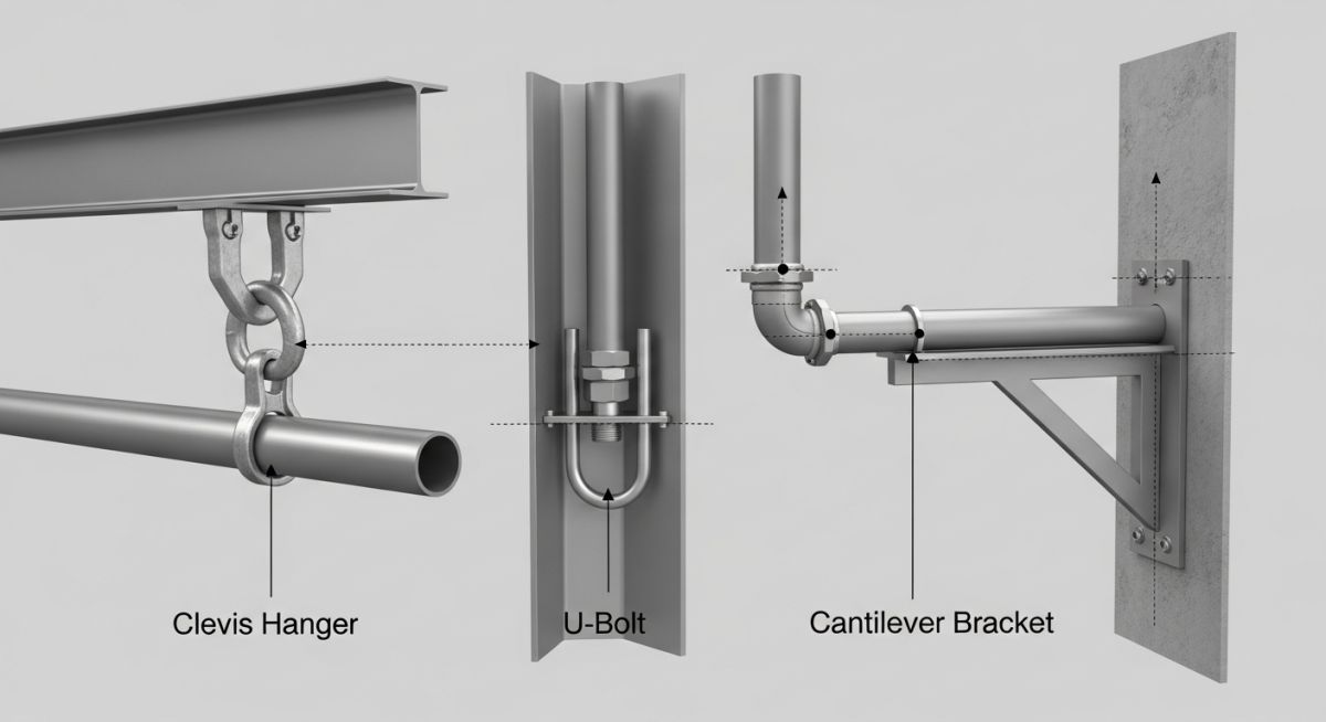
In my experience, the design of pipe support brackets requires a deep understanding of structural mechanics. We must evaluate the bracket as a cantilever or a beam element subjected to combined loading. The primary loads include the dead weight of the pipe, the weight of the fluid during operation, insulation weight, and dynamic forces such as wind, seismic activity, or water hammer.
To prevent structural failure, we calculate the maximum bending stress and deflection of the bracket. For a standard cantilever bracket supporting a concentrated load (P) at a distance (L) from the wall, the maximum bending moment (M) is calculated as:
The resulting bending stress (S) must not exceed the allowable stress of the material, typically specified by AISC or ASME standards:
Where Z is the section modulus of the bracket profile. Additionally, we must limit the maximum deflection (y) to prevent piping misalignment. For a cantilever beam with a concentrated load at the free end, the deflection is:
Where E is the Modulus of Elasticity of the material and I is the Moment of Inertia of the bracket cross-section. In standard industrial applications, we design for a maximum deflection of 2.5 millimeters or 0.1 inches to maintain proper slope and drainage.
Never weld a pipe directly to a support bracket unless the stress analysis explicitly permits it. Restricting thermal expansion on hot lines will generate massive thermal thrust forces, leading to bracket deformation, structural steel damage, or catastrophic nozzle failures at connected equipment.
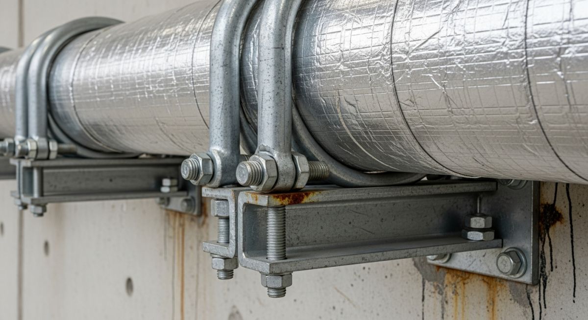
When selecting bracket materials, carbon steel (such as ASTM A36) is the industry standard for non-corrosive environments. For offshore platforms, chemical processing plants, or sanitary applications, we specify stainless steel (ASTM A312 or A240 Grade 316) or hot-dip galvanized finishes to prevent galvanic corrosion and environmental degradation.
The following tables provide standard engineering reference data for pipe support spacing and bracket load capacities. These values are based on carbon steel piping carrying water, in compliance with MSS SP-58 guidelines.
| Nominal Pipe Size (NPS) | Max Span for Water Service (m) | Max Span for Steam/Gas (m) | Recommended Bracket Load (kN) |
|---|---|---|---|
| 2 inch (DN 50) | 3.0 | 4.0 | 2.5 |
| 4 inch (DN 100) | 4.3 | 5.2 | 5.0 |
| 6 inch (DN 150) | 5.2 | 6.4 | 8.0 |
| 8 inch (DN 200) | 5.8 | 7.3 | 12.0 |
| 12 inch (DN 300) | 7.0 | 9.1 | 18.0 |
This matrix maps the core technical entities, structural acronyms, and physical parameters associated with pipe support design and their corresponding standard references.
| Entity / Acronym | Physical Parameter | Design Function | Standard Reference |
|---|---|---|---|
| MSS SP-58 | Materials & Design Loads | Standardizes pipe hanger and support selection | MSS Standards |
| ASME B31.3 | Allowable Stress Limits | Governs process piping design and structural integrity | ASME B31.3 |
| AISC 360 | Steel Member Strength | Specifies structural steel design criteria for brackets | AISC Specifications |
| ASTM A36 | Yield Strength (250 MPa) | Standard carbon steel material for structural brackets | ASTM Standards |
Installing Pipe Support Brackets on Site
During my field audits, I frequently observe installation errors that compromise the entire piping system. Proper installation requires strict adherence to engineering drawings and manufacturer specifications. The checklist below outlines the critical verification steps that every field engineer and inspector must perform before commissioning.
-
Structural Alignment: Verify that the bracket is perfectly level and perpendicular to the pipe run within a tolerance of +/- 1 degree. -
Anchor Bolt Torque: Ensure all concrete expansion anchors or structural steel bolts are torqued to the specified values using a calibrated torque wrench. -
Slide Plate Clearance: For sliding supports, confirm that PTFE or graphite slide plates are clean, free of debris, and have adequate travel clearance for thermal expansion. -
Weld Quality: Inspect all field welds on welded brackets using Non-Destructive Testing (NDT) methods, such as Dye Penetrant Testing (DPT) or Magnetic Particle Testing (MPT), in accordance with AWS D1.1. -
Insulation Protection: Verify that pipe shoes or insulation shields are installed correctly to prevent crushing of the insulation material at the support point.
Field Case Study: Real-World Application
At a major petrochemical refinery, a 10-inch high-pressure steam line experienced severe vibration, leading to the cracking of three consecutive cantilever support brackets. The original design had failed to account for dynamic fluid transients during startup. The resulting cyclic loading exceeded the fatigue limit of the ASTM A36 steel brackets, posing an immediate risk of line rupture.
My team was brought in to perform a comprehensive stress analysis using CAESAR II. We redesigned the support system by replacing the rigid cantilever brackets with heavy-duty, spring-loaded variable support brackets. We also added structural gussets to the remaining brackets to increase their stiffness and natural frequency, shifting them out of the resonance zone. The modification completely eliminated the fatigue cracking and reduced vibration levels by over 85 percent.
This case highlights the importance of dynamic load analysis. When designing support systems for high-temperature or high-pressure lines, always perform a dynamic simulation if fluid transients or mechanical vibrations are anticipated.
Frequently Asked Engineering Questions
What is the maximum allowable spacing for pipe support brackets?
How do you calculate the load capacity of a custom bracket?
Can I use carbon steel brackets on stainless steel piping?
What is the difference between a rigid support and a sliding support?
How does thermal expansion affect bracket design?
Which codes govern the design of pipe support brackets?

📚 Recommended Resources: Pipe Support Brackets
Read these Guides
Related posts:
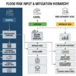
![Technical infographic showing the workflow of flood risk assessment for data centres, including hydrological inputs and mitigation strategies.]()
Flood Risk Assessment for Data Centres: Engineering Design Guide
![Isometric engineering rendering of a data centre campus featuring flood protection barriers and elevated utility infrastructure for disaster resilience.]()
Flood Protection Level Selection for Mission-Critical Data Centre Infrastructure
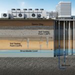
![Cross-section diagram of a data centre foundation showing soil strata, pile foundations, and groundwater monitoring wells for geotechnical analysis.]()
Geotechnical Requirements for Data Centres: A Structural Engineering Guide
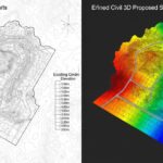
![Civil 3D interface showing a 3D site grading model with color-coded cut and fill zones for earthwork optimization.]()
Optimizing Cut and Fill Operations Using Civil 3D and GIS
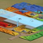
![3D digital terrain model showing site grading, flood protection levels, and cut-fill zones for industrial infrastructure development.]()
Establishing FPL and Estimating Cut Fill Quantities for Site Grading
![3D engineering model showing cut and fill optimization for industrial site grading and earthwork balancing.]()
Cut and Fill Optimization: 8 Engineering Studies for Site Grading