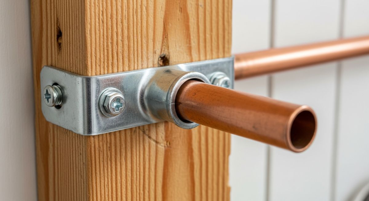
What is a Pipe Strap? Its Types, Importance, Materials, Applications
In my 20-plus years of managing piping systems in petrochemical plants and heavy industrial facilities, I have seen millions of dollars in equipment damaged by the failure of the simplest components. One such component is the humble pipe strap. Often dismissed as basic plumbing hardware, this small support is actually a critical element in maintaining the structural integrity of any piping network.
When a high-pressure line undergoes thermal expansion or experiences water hammer, the forces generated are immense. Without properly specified and installed straps, pipes will sag, vibrate, and eventually fail at their weakest joints. In this guide, I will share my field experience on how to select, calculate, and install these supports to ensure your systems remain safe, compliant, and highly reliable.
Key Takeaways
- Understand the mechanical differences between one-hole, two-hole, and heavy-duty straps.
- Learn how to calculate maximum support spans to prevent pipe sagging and deflection.
- Identify and prevent galvanic corrosion by matching strap materials to carrier pipes.
- Ensure compliance with industry standards including ASME B31.3 and MSS SP-58.
How Does a Pipe Strap Secure Industrial Piping?
Pipe Strap Mechanics: The primary mechanical function of a pipe strap is to restrict translational movement along the lateral and vertical axes while allowing controlled axial thermal expansion when specified. Proper selection prevents localized bending stresses and fatigue failures at critical joint interfaces under ASME B31.1 design conditions.
To design a safe piping system, we must treat every pipe strap as a structural boundary condition. Depending on the design, a strap can act as a rigid anchor (restricting all degrees of freedom) or as a guide (allowing axial movement while restricting lateral and vertical displacement).
Primary Types of Pipe Straps
In industrial applications, we classify these supports based on their geometry and load-bearing capacity:
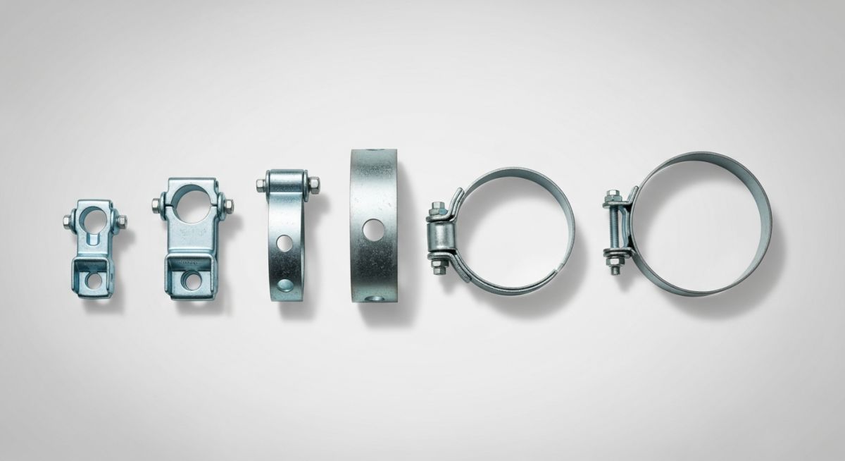
- One-Hole Straps: Feature a single mounting tab. These are ideal for light-duty, small-diameter lines (under 2 inches) where space is limited. They should not be used for high-vibration or heavy-fluid lines.
- Two-Hole Straps: Feature mounting tabs on both sides of the pipe. This design distributes the load evenly across two fasteners, making it the standard choice for industrial process piping.
- Heavy-Duty Clamping Straps: Manufactured from thicker gauge plate steel, often reinforced with a welded gusset. These are designed to handle high-load, high-vibration systems like reciprocating compressor discharge lines.
- Cushioned/Insulated Straps: Incorporate an elastomeric liner (such as EPDM, Neoprene, or TPE) between the metal strap and the pipe. The cushion dampens high-frequency vibrations and prevents galvanic corrosion.
Never install a bare carbon steel strap directly onto a copper or stainless steel pipe. The contact between dissimilar metals in the presence of moisture creates a galvanic cell, rapidly corroding the pipe wall and leading to catastrophic pinhole leaks. Always use copper-plated, plastic-coated, or cushioned straps for these materials.
Engineering Calculations for Support Spacing
To determine the maximum allowable span (L) between pipe straps to prevent excessive deflection, we use the standard beam deflection formula derived from structural mechanics:
Where:
- L = Maximum support span (inches)
- E = Modulus of elasticity of the pipe material (psi)
- I = Moment of inertia of the pipe cross-section (in⁴)
- y = Maximum allowable deflection (typically limited to 0.1 inches or 2.5 mm per ASME B31.3 to prevent liquid pocketing)
- w = Uniformly distributed weight of the pipe, including fluid and insulation (lbs/inch)
Additionally, we must calculate the tensile stress (S) in the strap band under a radial load (P) to ensure we do not exceed the yield strength of the strap material:
Where t is the thickness of the strap band (inches) and W is the width of the strap band (inches). The factor of 2 accounts for the two load-bearing sides of a standard two-hole strap. This stress must remain below the allowable design stress specified in ASME B31.3, incorporating a safety factor of at least 3:1.
The following table provides recommended maximum spacing and minimum strap thicknesses for carbon steel and stainless steel piping systems under standard operating conditions, in accordance with MSS SP-58 guidelines.
| Nominal Pipe Size (NPS) | Max Span (Water Service) | Max Span (Gas/Air Service) | Min Strap Thickness | Max Radial Load Limit |
|---|---|---|---|---|
| 1/2″ (DN 15) | 5.0 ft (1.5 m) | 6.0 ft (1.8 m) | 16 Gauge (1.5 mm) | 150 lbs (0.67 kN) |
| 1″ (DN 25) | 7.0 ft (2.1 m) | 9.0 ft (2.7 m) | 14 Gauge (2.0 mm) | 250 lbs (1.11 kN) |
| 2″ (DN 50) | 10.0 ft (3.0 m) | 13.0 ft (4.0 m) | 12 Gauge (2.7 mm) | 400 lbs (1.78 kN) |
| 3″ (DN 80) | 12.0 ft (3.7 m) | 15.0 ft (4.6 m) | 10 Gauge (3.4 mm) | 600 lbs (2.67 kN) |
| 4″ (DN 100) | 14.0 ft (4.3 m) | 17.0 ft (5.2 m) | 3/16″ Plate (4.8 mm) | 1,000 lbs (4.45 kN) |
Selecting the correct material and coating is critical to match the environmental conditions of your project site. This matrix maps common materials to their design limits and standard references.
| Material Type | Temperature Range | Corrosion Resistance | Primary Standard | Best Application |
|---|---|---|---|---|
| Carbon Steel (Pre-Galvanized) | -20°F to 450°F | Moderate (Indoor/Dry) | ASTM A653 | Commercial HVAC & Utility Lines |
| Hot-Dip Galvanized Steel | -20°F to 650°F | High (Outdoor/Humid) | ASTM A123 | Outdoor Pipe Racks & Water Treatment |
| 316 Stainless Steel | -320°F to 1200°F | Excellent (Marine/Chemical) | ASTM A240 | Offshore Platforms & Food/Pharma |
| Copper-Clad Steel | -20°F to 180°F | High (Specific to Copper) | MSS SP-58 Type 8 | Domestic Hot/Cold Water Lines |
How to Verify Pipe Strap Installation Quality?
Strap Installation Verification: Quality assurance for pipe strap installation requires systematic verification of fastener torque, material compatibility, and support spacing against isometric drawings. Adhering to these field checks ensures compliance with MSS SP-69 and prevents premature mechanical failure of the piping system.
During my field audits, I frequently find straps that were installed too tightly, crushing plastic pipes, or too loosely, allowing metal pipes to rattle and wear. Use this checklist on your job site to ensure every strap is installed to professional engineering standards.
Field Inspection Checkpoints
-
Material Compatibility: Verify that the strap material matches or is electrochemically isolated from the pipe material to prevent galvanic corrosion.
-
Fastener Engagement: Ensure anchors and screws have achieved full thread engagement in the structural substrate (concrete, steel, or wood) per manufacturer specifications.
-
Thermal Expansion Allowance: For hot lines, verify that the strap acts as a guide and does not pinch the pipe, allowing free axial movement without binding.
-
Span Compliance: Measure the distance between adjacent straps to confirm it does not exceed the maximum allowable span specified in the engineering drawings.
-
Cushion Integrity: Inspect elastomeric cushions for proper seating and ensure they are not pinched, torn, or displaced during the tightening process.
Why Select the Right Pipe Strap Material?
Strap Material Selection: Choosing the correct pipe strap material involves evaluating the operating temperature, environmental corrosivity, and electrochemical compatibility with the carrier pipe. Proper material matching prevents galvanic degradation and structural failure under severe service conditions.
In my career, I have seen many projects fail not because of poor hydraulic design, but because of a simple oversight in material selection for secondary supports. When a strap fails, the entire load shifts to adjacent supports, creating a domino effect that can bring down an entire pipe rack.
Field Case Study: Real-World Application
A chemical processing plant experienced repeated fatigue cracking at a welded branch connection on a 3-inch stainless steel condensate return line. The line operated at 280°F (138°C) and was subjected to severe cyclic thermal expansion and mechanical vibration. The original contractor had secured the line using standard, light-duty carbon steel two-hole straps bolted directly to structural steel channels without any isolation pads or thermal expansion clearance.
I led the engineering investigation and implemented a two-step remediation plan. First, we replaced the rigid carbon steel straps with heavy-duty, 316 stainless steel straps lined with high-temperature silicone cushions. Second, we recalculated the support span using ASME B31.3 guidelines, reducing the strap spacing from 12 feet to 8 feet to shift the system’s natural frequency away from the pump’s operating frequency. This modification reduced vibration amplitude by 85% and completely eliminated fatigue cracking over a 5-year monitoring period.
This case highlights why we must never treat pipe supports as an afterthought. Proper engineering analysis of thermal movement, vibration, and material compatibility is required for even the simplest pipe strap installation.
Frequently Asked Engineering Questions
What is the difference between a pipe strap and a pipe clamp?
How do you calculate the load capacity of a two-hole pipe strap?
Can pipe straps be used for thermal expansion loops?
What standards govern the design and installation of pipe straps?
How do you prevent galvanic corrosion when using pipe straps?
Are plastic pipe straps acceptable for industrial applications?
Complete Course on
Piping Engineering
Check Now
Key Features
- 125+ Hours Content
- 500+ Recorded Lectures
- 20+ Years Exp.
- Lifetime Access
Coverage
- Codes & Standards
- Layouts & Design
- Material Eng.
- Stress Analysis
