Table of Contents
How to Design Pipe Expansion Loops for Piping Systems
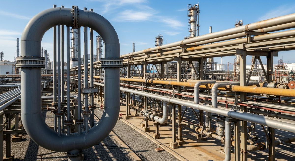
In my 20 plus years of experience in piping engineering, I have seen countless piping systems fail not because of pressure, but because of thermal expansion. When a pipe heats up, it expands with immense force. If you do not give that pipe room to move, it will find its own way to relieve that stress—usually by buckling, tearing out anchors, or causing catastrophic flange leaks. That is where pipe expansion loops come in. They are the simplest, most reliable, and most cost-effective way to introduce flexibility into a piping system without relying on mechanical expansion joints that are prone to bellows failure.
Designing these loops is not a matter of guesswork or copying a standard detail from a previous project. It requires a deep understanding of structural mechanics, material properties, and code compliance. In this guide, I will walk you through the exact engineering principles, calculations, and field realities I use to design and verify pipe expansion loops that stand the test of time.
Key Takeaways from This Guide:
- Master the guided cantilever method for accurate loop sizing.
- Calculate thermal expansion using mean coefficient values.
- Position anchors and guides to prevent lateral buckling.
- Verify stress compliance under ASME B31.3 Chapter II.
- Optimize loop leg lengths to minimize structural footprint.
How to Calculate Pipe Expansion Loops Correctly
When designing pipe expansion loops, our primary goal is to limit the displacement stress range to within the allowable limits defined by codes like ASME B31.3 Process Piping. The most common analytical method for sizing these loops is the Guided Cantilever Method. This method assumes that the expansion loop behaves as a series of guided cantilever beams absorbing the thermal expansion of the straight pipe runs.
The fundamental formula to calculate the required leg length of a pipe expansion loop is:
Where:
- L = Total loop leg length (inches)
- E = Modulus of elasticity of the pipe material at design temperature (psi)
- D = Outside diameter of the pipe (inches)
- Delta = Thermal expansion to be absorbed by the loop (inches)
- Sa = Allowable displacement stress range (psi) per ASME B31.3
To find the thermal expansion (Delta), we use the following relationship:
Where L_pipe is the length of the straight pipe run, alpha is the mean coefficient of thermal expansion, T_operating is the maximum operating temperature, and T_install is the minimum installation temperature.
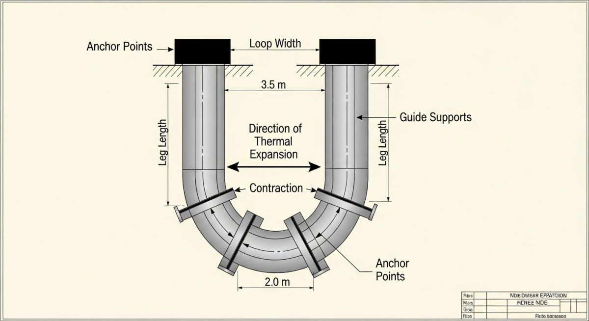
Field Warning: Guide Placement is Critical
Placing the first pipe guide too close to the loop elbow restricts the natural flexing of the loop. This causes localized overstress, flange leakage, and eventual anchor failure. Always position the first guide at a distance of 4 times the nominal pipe diameter (4D) from the loop elbow, and the second guide at 14 times the diameter (14D) from the first guide.
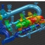
In my experience, many junior engineers forget to account for the stiffness of the elbows when using the guided cantilever method. Standard elbows are more flexible than straight pipe, which actually helps reduce the overall stress. However, to remain conservative, the guided cantilever formula assumes rigid corners. For highly critical or high-temperature lines, I always recommend verifying the manual calculations using a 3D pipe stress analysis software like CAESAR II to ensure compliance with ASME B31.1 Power Piping or B31.3.
The table below provides the thermal expansion rates for common piping materials at various operating temperatures, assuming an installation temperature of 70 degrees Fahrenheit. These values are derived from ASME B31.3 Appendix C.
| Material Specification | 100 F (in/100 ft) | 200 F (in/100 ft) | 300 F (in/100 ft) | 400 F (in/100 ft) | 500 F (in/100 ft) | 600 F (in/100 ft) |
|---|---|---|---|---|---|---|
| Carbon Steel (A106-B) | 0.23 | 0.99 | 1.82 | 2.69 | 3.62 | 4.60 |
| Stainless Steel (A312-TP304) | 0.34 | 1.47 | 2.63 | 3.83 | 5.08 | 6.36 |
| Chrome-Moly (A335-P11) | 0.22 | 0.95 | 1.73 | 2.56 | 3.43 | 4.35 |
This matrix maps the core technical entities, structural acronyms, physical parameters, and governing standards required for designing robust pipe expansion loops.
| Parameter / Entity | Acronym / Symbol | Physical Unit | Governing Standard | Design Impact |
|---|---|---|---|---|
| Modulus of Elasticity | E | psi / MPa | ASME B31.3 | Determines material stiffness and resistance to bending deformation. |
| Allowable Stress Range | Sa | psi / MPa | ASME B31.3 Section 302.3.5 | The maximum stress range allowed to prevent fatigue failure over the design life. |
| Thermal Expansion Coefficient | alpha | in/in/F / mm/mm/C | ASME B31.3 Appendix C | Controls the total linear expansion rate per unit length of pipe. |
| Guided Cantilever Length | L | ft / m | Industry Standard Practice | Defines the physical dimensions of the loop legs to absorb thermal growth. |
Site Verification Checklist for Pipe Expansion Loops
Even the most perfect engineering design can fail if the field installation is executed incorrectly. Over my career, I have seen field crews weld up expansion loops without checking guide clearances or, worse, install rigid supports where guides were specified. Use this checklist on-site to ensure your pipe expansion loops are installed correctly.
On-Site Inspection Checklist:
-
✓
Verify that cold spring (if specified) is executed per the engineering drawing and documented. -
✓
Confirm that the first guide (G1) is located at exactly 4 times the pipe diameter (4D) from the loop elbow. -
✓
Ensure the second guide (G2) is positioned at 14 times the pipe diameter (14D) from G1. -
✓
Check that anchors are fully welded or bolted to structural steel capable of resisting the calculated thermal thrust forces. -
✓
Inspect the loop elbows for correct wall thickness (typically long-radius elbows are required per ASME B16.9). -
✓
Verify that no temporary shipping bars or construction restraints remain on the expansion loop. -
✓
Confirm that insulation clearances allow for the full calculated lateral movement of the loop legs.
Field Case Study: Real-World Application
The Problem:
A 12-inch high-pressure steam line (600 psig, 650 degrees Fahrenheit) in a petrochemical plant experienced severe anchor displacement and flange leakage at a turbine inlet. The original design used a rigid layout with insufficient flexibility, and the field team had omitted the calculated pipe expansion loops to save space.
The Outcome:
I was called to perform an emergency stress analysis. We redesigned the system by introducing a symmetric 3D pipe expansion loop with a 15-foot leg length. Using CAESAR II, we verified that the expansion stresses dropped from 45,000 psi (overstressed) to 12,500 psi (well within the ASME B31.3 allowable limit of 22,500 psi). The flange leakage was completely resolved, and the turbine nozzle loads were reduced by 75%.
My direct recommendation for any high-temperature piping system is to never compromise on loop dimensions. If space is tight, consider a 3D loop configuration or offset routing rather than reducing the calculated leg length of your pipe expansion loops.
Frequently Asked Engineering Questions
What is the primary purpose of pipe expansion loops in high-temperature systems?
How do you determine the location of anchors relative to pipe expansion loops?
Can we use short-radius elbows in pipe expansion loops?
What is cold spring, and should it be used in pipe expansion loops?
How does pipe wall thickness affect the design of pipe expansion loops?
When should an expansion joint be used instead of a pipe expansion loop?
Complete Course on
Piping Engineering
Check Now
Key Features
- 125+ Hours Content
- 500+ Recorded Lectures
- 20+ Years Exp.
- Lifetime Access
Coverage
- Codes & Standards
- Layouts & Design
- Material Eng.
- Stress Analysis

📚 Recommended Resources: pipe expansion loops
Read these Guides
🎓 Advanced Training


Related posts:
![Super duplex stainless steel piping network on an offshore oil drilling platform.]()
Super Duplex Stainless Steel Oil and Gas Piping Design Guide
![Industrial duplex stainless steel piping system in a chemical processing facility.]()
Understanding Duplex Stainless Steel Properties and Industrial Piping Applications
![A welder performing a critical golden joint weld on an industrial steel pipeline.]()
What is a Golden Joint in Piping Systems?
![A collection of different types of industrial pipes classified by material and size on a storage rack.]()
Comprehensive Guide to Types of Pipes and Industrial Classification Systems
![Industrial piping network with digital overlays representing inch-dia and inch-meter engineering calculations.]()
What are Inch-Dia and Inch-Meter in Piping Systems?
![3D finite element stress analysis model of an industrial piping system showing stress distribution.]()
What Causes Piping System Stresses in Industrial Plants?