Table of Contents
What is a Pinch Valve? Working, Types, and Selection
In my 20 plus years of piping engineering, I have seen countless standard valves fail prematurely when handling aggressive media. Slurries, dry solids, and highly corrosive chemicals eat away at metal seats, plug up cavities, and seize up actuators. When I am faced with these severe service conditions, my go-to solution is often the pinch valve. It is elegant in its simplicity: a flexible sleeve is compressed to shut off flow. There are no pockets for solids to settle, no metal seats to erode, and the process fluid never contacts the valve’s mechanical parts. Let me share my field-tested insights on how these valves operate, how to select the right elastomer, and how to avoid common installation pitfalls.
Key Engineering Takeaways
- Complete isolation of process media from mechanical components prevents corrosion and mechanical seizing.
- Full-bore design ensures zero flow restriction and minimal pressure drop across the valve.
- Elastomer sleeve selection is the single most critical factor for valve longevity and chemical compatibility.
- Pneumatic pinch valves offer rapid actuation but require precise control of differential operating pressure.
- Mechanical pinch valves provide positive shutoff even against high line pressures and vacuum conditions.
How Does a Pinch Valve Control Flow?
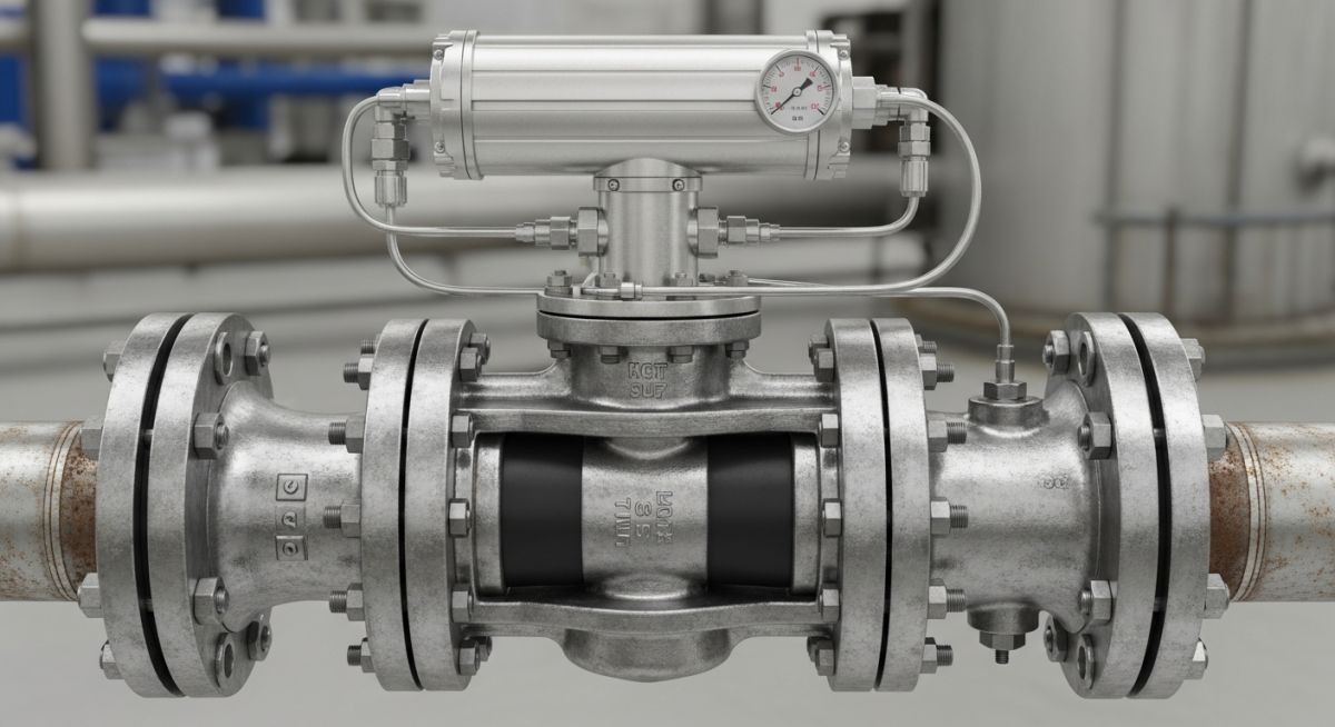
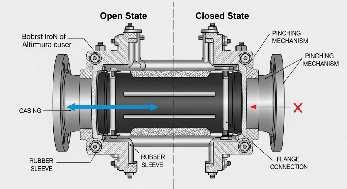
To truly appreciate this technology, we must look at the two primary methods of sleeve compression: pneumatic (air-operated) and mechanical. In a pneumatic pinch valve, compressed air or hydraulic fluid is introduced directly into the valve body housing. As the jacket pressure increases, it overcomes the internal line pressure and the natural elasticity of the sleeve, forcing the sleeve to collapse in a flat, horizontal profile. This method is highly efficient for rapid on-off cycling.
Conversely, mechanical pinch valves utilize one or two internal compressor bars driven by a threaded spindle, handwheel, or external actuator. In a double-pinch design, which I highly recommend for larger line sizes, two compressor bars squeeze the sleeve symmetrically from both the top and bottom. This dual-sided compression minimizes localized stress on the elastomer fold lines, significantly extending the service life of the sleeve.
Sleeve Collapse Pressure Calculations
To determine the required control pressure (Pc) for a pneumatic pinch valve, we use the formula:
Pc = Pl + Ps
Where Pl is the process line pressure and Ps is the sleeve pre-tension or collapse resistance pressure. The collapse resistance pressure of an unsupported cylindrical elastomer sleeve can be estimated using the classical shell buckling equation:
Ps = (2 * E / (1 – nu^2)) * (t / D)^3
In this equation, E represents the Young’s modulus of the elastomer material, nu is the Poisson’s ratio (typically close to 0.5 for rubber), t is the sleeve wall thickness, and D is the mean diameter of the sleeve. For example, in a system with a process line pressure of 4 bar, if the sleeve collapse resistance is calculated as 1.5 bar, the minimum control air pressure required to achieve positive shutoff is 5.5 bar.
Design limitations are primarily governed by temperature and pressure. Because the pressure-retaining boundary relies on an elastomer, these valves are generally limited to lower pressure classes, typically up to 16 bar (230 psi) for smaller sizes, and dropping significantly as nominal pipe size increases. Temperature limits are capped by the elastomer’s thermal threshold, typically around 150 degrees Celsius for specialized materials like Viton or EPDM. Testing and design parameters must align with ASME B16.34 and API 598.
Selecting the correct elastomer is the single most critical decision in pinch valve engineering. The table below outlines the physical properties and chemical compatibility of common sleeve materials in accordance with ASTM D2000 standards.
| Elastomer Material | ASTM Designation | Temp Range (°C) | Chemical Resistance | Common Applications |
|---|---|---|---|---|
| Natural Rubber (NR) | AA, BA | -30 to +80 | Excellent abrasion, weak acids | Mining slurries, sand, cement |
| EPDM | CA, DA | -40 to +130 | Ozone, ketones, dilute acids | Wastewater, chemical processing |
| Nitrile (NBR) | CH, HB | -20 to +100 | Oils, fats, hydrocarbons | Oily slurries, food processing |
| Viton (FKM) | HK | -10 to +180 | Strong acids, high heat, solvents | Petrochemicals, aggressive acids |
| Neoprene (CR) | BC, BE | -30 to +100 | Moderate weathering, mild oils | Marine applications, general utility |
This matrix maps core technical entities, structural acronyms, and physical parameters to their respective industry standards, providing a quick reference for piping designers.
| Parameter / Entity | Acronym / Code | Physical Specification | Standard Reference |
|---|---|---|---|
| Sleeve Wall Thickness | t | 6 mm to 15 mm (size dependent) | ASME B31.3 |
| Control Pressure Differential | Delta P | 1.5 to 2.5 bar above line pressure | ISA 75.01 |
| Shell Pressure Test | Psist | 1.5 times design pressure | API 598 |
| Seat Leakage Class | Class VI | Zero bubbles (bubble-tight) | FCI 70-2 |
| Face-to-Face Dimensions | FTF | Manufacturer standard or ASME B16.10 | ASME B16.10 |
How to Inspect a Pinch Valve?
Before installing any pinch valve into a process line, a rigorous field inspection must be performed. Because the sleeve is the only pressure-retaining and moving part, any misalignment or incorrect actuator calibration will lead to rapid failure. I always insist on a dry-run stroke test and a visual inspection of the elastomer’s surface integrity prior to bolt-up.
Field Installation Checklist
-
Verify that the elastomer sleeve material matches the piping specification sheet (e.g., EPDM vs. Natural Rubber) by checking the molded-in identification tag. -
Inspect the internal bore for any manufacturing defects, pinholes, or surface gouges that could compromise the pressure boundary. -
Confirm that the control air regulator is calibrated to deliver no more than the maximum allowable differential pressure specified by the manufacturer. -
Ensure the valve is installed with sufficient clearance to allow for sleeve replacement without dismantling the entire piping spool. -
Check that the flange bolts are torqued in a star pattern to the exact values specified, preventing over-compression of the sleeve’s integral flange gaskets.
Field Case Study: Real-World Application
The Challenge: Rapid Valve Erosion in Mining Slurry
A copper mining facility in Chile was experiencing catastrophic failures of standard metal-seated knife gate valves on their primary tailings slurry line. The slurry contained 45% abrasive silica solids by weight, operating at a line pressure of 6 bar. The metal seats eroded within 3 weeks of installation, causing severe external leakage and process downtime that cost the plant over 45,000 per hour in lost production.
The Solution & Outcome
As the lead piping consultant, I recommended retrofitting the line with a heavy-duty, enclosed-body mechanical double-pinch valve equipped with a high-tensile natural rubber sleeve. The double-pinch mechanism compressed the sleeve symmetrically from both sides, minimizing localized stress. After installation, the valve operated continuously for 18 months without a single leak or drop in performance. When the sleeve was finally replaced during scheduled maintenance, the mechanical actuator and valve body were found to be in pristine condition, completely untouched by the abrasive slurry.
For highly abrasive slurry applications with high solids content, always specify a mechanical double-pinch valve with a natural rubber sleeve to isolate the mechanical components and maximize service life.
Common Pinch Valve Questions Answered
Can pinch valves be used in vacuum service?
What is the typical lifespan of a pinch valve sleeve?
How do you determine the correct control air pressure for a pneumatic pinch valve?
Can a pinch valve be used for throttling or control applications?
What standards govern the testing and design of pinch valves?
What are the primary failure modes of a pinch valve?
===
Complete Course on
Piping Engineering
Check Now
Key Features
- 125+ Hours Content
- 500+ Recorded Lectures
- 20+ Years Exp.
- Lifetime Access
Coverage
- Codes & Standards
- Layouts & Design
- Material Eng.
- Stress Analysis

📚 Recommended Resources: Pinch Valve
Read these Guides


Related posts:
![Piping stress engineer analyzing 3D piping model on computer screen for stress analysis]()
Mastering Piping Stress Interview Questions: The Ultimate Engineering Guide
![Industrial steam jet ejector 3D CAD model showing inlet and discharge ports]()
What is an Ejector? Types, Parts, Datasheet, and Working Principles
![3D CAD model of industrial piping system showing color-coded piping classes and specifications.]()
Mastering the Piping Material Specification for Industrial Plant Design
![Industrial pig launcher and receiver station with quick-opening closure and bypass piping.]()
Design and Engineering of Pig Launchers and Receivers
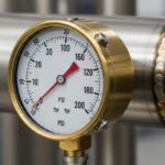
![Close-up of an industrial dial pressure gauge mounted on a stainless steel pipe.]()
What is a Pressure Gauge and How Does It Work?
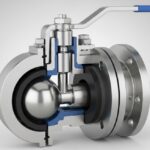
![3D cutaway diagram of an industrial ball valve showing internal components like the ball, stem, and seats.]()
What is a Ball Valve? Design, Types, and Engineering Standards