Table of Contents
Design and Engineering of Pig Launchers and Receivers
In my 20 years of commissioning pipeline systems across the globe, I have seen many young engineers treat pig traps as simple, oversized pipes. That is a dangerous mistake. These components are highly engineered pressure vessels subject to severe cyclic stresses, thermal expansion, and unpredictable dynamic forces during pig transit. Whether you are clearing paraffin wax from a crude line or running an intelligent magnetic flux leakage (MFL) tool to detect corrosion, the design of your launcher and receiver station dictates the safety of your entire field crew.
When a pig travels at 5 meters per second and hits a receiver barrel, the kinetic energy transfer is immense. If your bypass lines, kicker lines, and quick-opening closures are not engineered with precision, you risk catastrophic pressure containment loss. In this guide, I will walk you through the exact design calculations, code requirements, and field realities that I use to design safe, high-performance pigging stations.
Key Engineering Takeaways
- Understand the critical dimensional differences between major and minor barrels.
- Master the wall thickness calculations under ASME B31.4 and B31.8 codes.
- Learn how to size kicker, bypass, and drain lines to prevent pig stalling.
- Implement mandatory safety interlocks on quick-opening closures to protect field operators.
How to Design Pig Launchers and Receivers
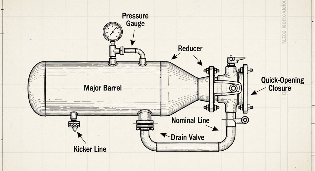
The physical geometry of a pig trap is divided into two primary sections: the major barrel (the oversized section where the pig is loaded or retrieved) and the minor barrel (which matches the nominal pipeline diameter). Connecting these two sections is a concentric or eccentric reducer.
1. Barrel Diameter Sizing
The major barrel diameter must be larger than the nominal pipeline diameter to allow the pig to be easily inserted (in launchers) or to allow the bypass fluid to flow around the pig as it comes to a stop (in receivers).
- For pipelines up to 10 inches: The major barrel diameter is typically 2 inches larger than the nominal pipeline size.
- For pipelines 12 inches and larger: The major barrel diameter is typically 4 inches larger than the nominal pipeline size to accommodate heavy intelligent pigs and cup deflection.
2. Barrel Length Sizing
The length of the major barrel depends on the type of pigs you plan to run. Standard utility pigs (foam, cup, or brush pigs) are relatively short. However, intelligent inspection tools (smart pigs) require significantly longer barrels due to their multi-module sensor arrays.
The formula I use to determine the minimum major barrel length (Lm) for a launcher is:
Where L_pig is the length of the longest intelligent pig expected to be used during the pipeline’s design life. For receivers, the major barrel length is typically longer to allow for debris accumulation ahead of the pig:
3. Wall Thickness Calculations
Because pig traps are located at pipeline terminals, they are subject to the design codes of the adjacent pipeline. For liquid pipelines, we design under ASME B31.4. For gas pipelines, we design under ASME B31.8.
The nominal wall thickness (t) of the major barrel is calculated using the Barlow’s formula modified by the design factors:
Where:
P = Internal design pressure (psig or barg)
D = Outside diameter of the major barrel (inches or mm)
S = Specified Minimum Yield Strength (SMYS) of the steel (psi or MPa)
F = Design factor (typically 0.60 or 0.50 for terminal piping near stations, depending on location class)
E = Longitudinal joint factor (1.0 for seamless or high-quality submerged arc welded pipe)
T = Temperature derating factor (1.0 for operating temperatures below 250°F / 121°C)
4. Kicker and Bypass Line Sizing
The kicker line is the piping that diverts flow from the main pipeline into the back of the pig launcher to push the pig forward, or diverts flow from the receiver to pull the pig in.
In my experience, sizing the kicker line too small is the leading cause of stalled pigs. The kicker line should be sized to handle at least 30% to 50% of the total pipeline flow rate. For gas lines, the velocity in the kicker line should not exceed 20 meters per second to prevent severe vibration and erosion.
Below is the standard engineering dimension matrix that I have developed over years of executing pipeline projects. These dimensions serve as an excellent starting point for front-end engineering design (FEED) packages.
| Nominal Pipe Size (inches) | Major Barrel Size (inches) | Launcher Major Length Lm (mm) | Receiver Major Length Lm (mm) | Kicker Line Size (inches) |
|---|---|---|---|---|
| 6 | 8 | 1200 | 1800 | 2 |
| 12 | 16 | 1800 | 2400 | 4 |
| 24 | 28 | 2800 | 3600 | 8 |
| 36 | 40 | 3500 | 4800 | 12 |
This matrix maps the core technical entities, structural acronyms, and physical parameters of pig traps to their governing international standards.
| Component / Parameter | Acronym | Primary Function | Governing Code / Standard |
|---|---|---|---|
| Quick Opening Closure | QOC | Provides rapid access to the barrel for loading/retrieval | ASME Sec VIII Div 1 / UG-35.2 |
| Pig Signaller / Indicator | PIGSIG | Detects the physical passage of the pig past a specific point | Manufacturer Standard / API 6D |
| Specified Minimum Yield Strength | SMYS | Defines the plastic deformation limit of the steel barrel | API Spec 5L / ASTM A106 |
| Pressure Safety Valve | PSV | Protects the barrel from overpressurization during isolation | ASME Sec VIII Div 1 |
Pre-Commissioning Checklist for Pig Launchers and Receivers
Before you sign off on a newly installed pig launcher or receiver station, you must perform a comprehensive field walkdown. Below is the exact checklist I use to verify that the installation matches the engineering design and is safe for live operations.
Field Inspection & Commissioning Protocol
-
Verify QOC Safety Interlock: Ensure the mechanical safety interlock on the quick-opening closure is fully functional. The interlock must physically prevent the door from opening if there is any residual pressure (even as low as 0.05 barg) inside the barrel.
-
Check Reducer Orientation: For pig receivers, verify that an eccentric reducer is installed with the flat side on the bottom (flat-on-bottom). This prevents liquids and debris from pooling at the transition point, which can cause localized corrosion.
-
Inspect Pig Signaller Alignment: Ensure the mechanical trigger or non-intrusive magnetic sensor of the pig signaller is positioned correctly. Intrusive triggers must be checked for correct insertion depth to prevent them from being sheared off by the pig.
-
Validate Vent and Drain Routing: Confirm that the barrel vents are routed to a safe location (flare or high-point vent) and that the drains are routed to the closed drain system. Drains must never be discharged directly to the ground.
-
Confirm Grounding and Bonding: Verify that the launcher/receiver barrel is electrically bonded to the main pipeline and connected to the facility grounding grid to prevent static electricity buildup during pigging operations.
Field Case Study: Real-World Application
The Problem: Pig Stalling and Pressure Spikes in a Wet Gas Line
During the commissioning of a 24-inch wet gas pipeline in the Middle East, the field operators experienced repeated pig stalling inside the receiver’s minor barrel. When the pig stalled, the upstream pressure rapidly spiked by 15 barg, threatening to trigger an emergency shutdown (ESD) of the upstream production facility.
Upon investigation, I discovered that the original engineering design had specified a kicker line that was only 4 inches in diameter (less than 17% of the main pipeline size). This restricted the bypass flow rate, leaving insufficient differential pressure across the pig to push it through the concentric reducer into the major barrel.
To resolve this issue without replacing the entire receiver vessel, I led a fast-track engineering modification. We hot-tapped the receiver to install an auxiliary 8-inch kicker line, effectively increasing the bypass flow capacity to 40% of the total pipeline flow.
We also replaced the standard concentric reducer with an eccentric flat-on-bottom reducer during a scheduled maintenance shutdown. This modification allowed the heavy liquids swept by the pig to drain freely into the liquid collection system rather than pooling at the reducer face.
Frequently Asked Engineering Questions
What is the difference between a pig launcher and a pig receiver?
Why are eccentric reducers preferred over concentric reducers for pig receivers?
Which ASME codes govern the design of pig launchers and receivers?
What is the purpose of a kicker line in a pigging system?
How do safety interlocks work on quick-opening closures?
Why is a balance line required on a pig receiver?
===FAQ_BLOCK===
Complete Course on
Piping Engineering
Check Now
Key Features
- 125+ Hours Content
- 500+ Recorded Lectures
- 20+ Years Exp.
- Lifetime Access
Coverage
- Codes & Standards
- Layouts & Design
- Material Eng.
- Stress Analysis

📚 Recommended Resources: pig launchers and receivers
Related posts:
![Piping stress engineer analyzing 3D piping model on computer screen for stress analysis]()
Mastering Piping Stress Interview Questions: The Ultimate Engineering Guide
![Industrial steam jet ejector 3D CAD model showing inlet and discharge ports]()
What is an Ejector? Types, Parts, Datasheet, and Working Principles
![3D CAD model of industrial piping system showing color-coded piping classes and specifications.]()
Mastering the Piping Material Specification for Industrial Plant Design
![Close-up of an industrial dial pressure gauge mounted on a stainless steel pipe.]()
What is a Pressure Gauge and How Does It Work?
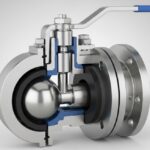
![3D cutaway diagram of an industrial ball valve showing internal components like the ball, stem, and seats.]()
What is a Ball Valve? Design, Types, and Engineering Standards
![3D cross-section diagram of a hydraulic fracturing rig drilling into underground shale rock formations.]()
What is Fracking and How Does Hydraulic Fracturing Work?