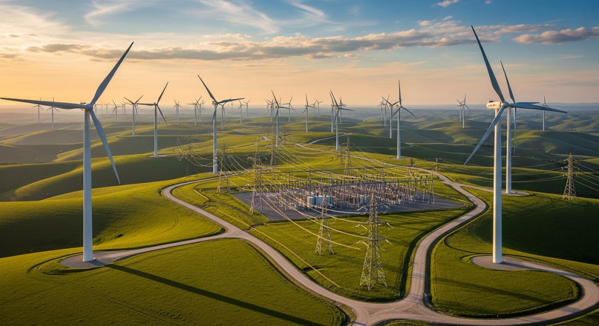
Onshore Wind Farms: Design, Components and Applications Introduction
In my two decades of experience across industrial infrastructure, I have observed that the successful deployment of onshore wind farms requires far more than simply erecting turbines in windy locations. It is a complex orchestration of geotechnical site assessment, aerodynamic optimization, and high-voltage electrical engineering.
Engineers must balance the mechanical loads imposed by turbulent wind regimes with the stringent requirements of local grid codes. Whether you are managing the foundation design or the substation integration, understanding the interplay between these components is vital for project longevity.
Key Takeaways for Engineering Success:
- Rigorous wind resource assessment is the foundation of project bankability.
- Turbine layout optimization minimizes wake effects and maximizes annual energy production.
- Grid connection compliance requires precise reactive power control and harmonic mitigation.
- Construction logistics demand careful planning for heavy-lift crane access and component transport.
Technical Design of Onshore Wind Farms
Onshore Wind Farm Design: The integration of mechanical, electrical, and civil engineering disciplines to convert kinetic wind energy into grid-compliant electricity while adhering to ASME and IEEE standards.
The core of any onshore wind farm project is the wind resource assessment. We utilize anemometry and LiDAR data to calculate the Weibull distribution of wind speeds at the site. The power available in the wind is proportional to the cube of the wind speed, expressed as P = 0.5 * rho * A * v^3, where rho is air density, A is the swept area, and v is wind velocity.
Foundation design is equally critical. For modern turbines, we typically employ gravity-based reinforced concrete foundations or rock-anchor systems. The design must account for the overturning moment caused by the thrust force at the hub height. We calculate this using the formula M = F_thrust * H_hub, where F_thrust is the aerodynamic load and H_hub is the height of the rotor center.
Field Warning: Soil-Structure Interaction
In my experience, neglecting the dynamic soil-structure interaction during the geotechnical phase leads to premature foundation fatigue. Always perform site-specific seismic analysis and ensure the foundation natural frequency avoids the 1P and 3P rotor frequencies to prevent resonance.
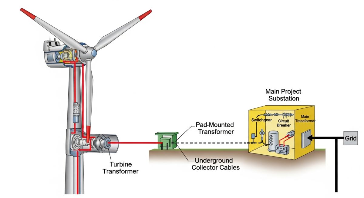
Electrical infrastructure involves a medium-voltage collection system, typically 33kV or 34.5kV, connecting individual turbines to a central substation. The collection cables are usually buried to minimize environmental impact and protect against lightning strikes. At the substation, a step-up transformer increases the voltage to the transmission level, often 115kV to 230kV, to minimize resistive losses during transport.
Grid connection compliance is governed by strict grid codes. We must implement power factor control and fault ride-through capabilities. Modern turbines use power electronics, specifically full-scale converters, to decouple the generator frequency from the grid frequency, allowing for variable speed operation which significantly improves aerodynamic efficiency.
Onshore Wind Farm Performance: A comparative analysis of the operational benefits and technical challenges inherent in land-based wind energy infrastructure.
Advantages
- Lower capital expenditure compared to offshore installations.
- Simplified logistics for component transport and heavy-lift crane mobilization.
- Easier access for routine maintenance and component replacement.
- Proven technology with extensive global supply chain support.
- Rapid deployment timelines for modular turbine designs.
Disadvantages
- Lower average wind speeds compared to offshore environments.
- Significant land footprint requirements for turbine spacing and access roads.
- Potential for noise and visual impact concerns in populated areas.
- Intermittency issues requiring grid-scale energy storage integration.
- Complex permitting and environmental impact assessment processes.
Onshore Wind Farm Deployment: Strategic implementation of wind energy systems across diverse industrial and utility-scale sectors to achieve decarbonization goals.
Industrial Feedstock Decarbonization
Large-scale manufacturing facilities utilize dedicated onshore wind farms to provide direct power to energy-intensive processes. By integrating behind-the-meter wind generation, these plants reduce reliance on fossil-fuel-based grid power and stabilize long-term energy costs through power purchase agreements.
Green Hydrogen Production
Onshore wind farms are increasingly coupled with electrolyzer plants to produce green hydrogen. The variable output of the wind farm is managed through advanced control systems to ensure the electrolyzers operate within optimal efficiency ranges, effectively storing excess wind energy as chemical fuel.
Utility-Scale Grid Support
Regional utilities deploy onshore wind farms to provide bulk energy to the national grid. These projects are designed to meet stringent grid code requirements, including reactive power support and frequency regulation, acting as a primary pillar of the transition to a low-carbon energy mix.
In my two decades of experience, I have found that selecting the correct turbine class is the most critical decision for project viability. The following table outlines the standard IEC 61400-1 design classes, which dictate the structural integrity requirements based on extreme wind speeds and turbulence intensity. Engineers must reconcile these site-specific parameters with the turbine’s power curve to ensure the project remains within the fatigue load limits defined by the manufacturer.
When reviewing these parameters, consider the hub height and the shear exponent, as these significantly influence the annual energy production (AEP) calculations. Discrepancies between the site wind resource assessment and the turbine’s design class often lead to premature component failure, particularly in the gearbox and blade root connections. Always verify that your site’s 50-year extreme wind speed does not exceed the design limit of the selected turbine model.
| Turbine Class | Extreme Wind (m/s) | Avg Wind (m/s) | Turbulence Intensity |
|---|---|---|---|
| Class IA | 50 | 10.0 | 0.18 |
| Class IIA | 42.5 | 8.5 | 0.18 |
| Class IIIA | 37.5 | 7.5 | 0.18 |
These classifications serve as the baseline for structural design. If your site exhibits higher turbulence than the class allows, you must apply a site-specific load assessment to avoid voiding the warranty or risking structural collapse during extreme weather events.
The successful integration of onshore wind farms requires a deep understanding of the interconnected technical entities that govern power generation and grid stability. This matrix maps the primary components to their respective engineering standards and physical parameters, providing a clear reference for project managers and electrical engineers tasked with system design.
By aligning these entities with the appropriate IEC and IEEE standards, we ensure that the electrical infrastructure, from the turbine transformer to the substation, meets the stringent requirements for power quality and fault ride-through capability. This matrix is intended to be used as a high-level audit tool during the preliminary design phase to ensure no critical system interface is overlooked.
| Entity | Standard | Primary Parameter |
|---|---|---|
| Rotor Blades | IEC 61400-5 | Aerodynamic Torque |
| Power Converter | IEEE 519 | Harmonic Distortion |
| Foundation | ACI 318 | Overturning Moment |
Always cross-reference these standards with local grid codes, as regional requirements for reactive power support and frequency regulation often exceed the baseline international standards listed here.
Site verification is the final gate before mobilization. In my experience, failing to account for geotechnical variability or logistical constraints during the pre-construction phase leads to massive cost overruns. Use this checklist to ensure your site is ready for the heavy-lift equipment and electrical installation teams.
- ✓ Geotechnical soil bearing capacity verified for turbine foundation loads per ASCE standards.
- ✓ Access road turning radii confirmed for 60-meter blade transport trailers.
- ✓ Grid connection point (Point of Interconnection) impedance testing completed.
- ✓ Environmental impact mitigation measures (noise/shadow flicker) documented and approved.
- ✓ Crane pad compaction levels tested to meet minimum pressure requirements.
Each item on this list represents a potential project-killer if ignored. For instance, if the crane pad is not compacted to the specific PSI required by the turbine manufacturer, the crane may sink during the nacelle lift, causing catastrophic damage. Always maintain a signed-off copy of these verifications in the project file for insurance and compliance audits.
Field Case Study: Real-World Application
The Problem: Unexpected Foundation Settlement
A 50MW wind farm project experienced significant foundation settlement during the commissioning phase due to unforeseen subsurface water pockets.
- Inadequate initial geotechnical borehole density.
- High water table levels not accounted for in the seasonal variance study.
- Excessive vibration during turbine testing exacerbating soil liquefaction.
The Outcome: Successful Remediation and Stabilization
The project team implemented a rapid stabilization program that saved the project from total abandonment.
- Injection of high-density polyurethane grout to stabilize the soil matrix.
- Installation of additional deep-bored piles to redistribute the overturning moment.
- Implementation of real-time structural health monitoring sensors on all foundations.
My recommendation for future projects is to always perform a secondary geotechnical review if the site is located in a flood-prone or alluvial soil region. Do not rely solely on the preliminary survey; invest in deep-bore testing at every turbine location to mitigate these high-risk scenarios.
Frequently Asked Engineering Questions
How is the wind resource assessment validated?
- Use Measure-Correlate-Predict (MCP) methods to extend short-term site data.
- Verify anemometer calibration against MEASNET standards.
- Account for air density variations based on site elevation and temperature.
- Perform uncertainty analysis to ensure P50 and P90 energy yield estimates are statistically robust.
What are the primary grid connection challenges?
- Fault Ride-Through (FRT) capability is mandatory to prevent cascading grid failures.
- Harmonic mitigation is required to comply with IEEE 519 standards.
- Reactive power compensation is often needed to manage voltage fluctuations at the point of common coupling.
- Substation design must account for the intermittent nature of wind energy to avoid thermal overloading of transformers.
How do you optimize turbine layout for wake effects?
- Utilize computational fluid dynamics (CFD) models to simulate wind flow patterns.
- Maintain minimum spacing of 5 to 7 rotor diameters in the prevailing wind direction.
- Consider terrain-induced turbulence when placing turbines on ridges or complex slopes.
- Iterate the layout to maximize AEP while staying within the structural fatigue limits of the turbine blades.
What are the key O&M requirements?
- Implement condition-based monitoring (CBM) for gearboxes and main bearings.
- Schedule biannual inspections of blade leading edges for erosion and structural cracks.
- Maintain a robust spare parts inventory for critical components like pitch actuators and power electronics.
- Ensure all O&M activities comply with local health and safety regulations for working at heights.
How is foundation design determined?
- Calculate the overturning moment based on the maximum thrust force at the hub height.
- Design for soil-structure interaction to prevent long-term settlement or tilting.
- Use high-strength reinforced concrete per ACI 318 standards.
- Incorporate anchor bolt cages with precise tolerances to ensure the tower base remains perfectly vertical.
What is the role of SCADA in wind farms?
- Provide real-time monitoring of power output, wind speed, and turbine status.
- Enable remote control of turbine yaw and pitch for optimal power capture.
- Log historical performance data for trend analysis and predictive maintenance.
- Facilitate communication between the wind farm and the grid operator for dispatch and curtailment commands.
Complete Course on
Piping Engineering
Check Now
Key Features
- 125+ Hours Content
- 500+ Recorded Lectures
- 20+ Years Exp.
- Lifetime Access
Coverage
- Codes & Standards
- Layouts & Design
- Material Eng.
- Stress Analysis
