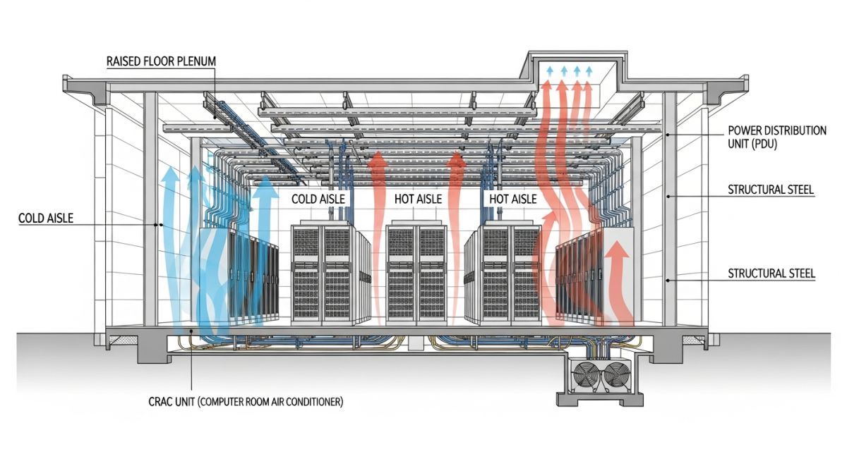
Designing a Modern Data Centre: Engineering and EPC Considerations
In my two decades of managing complex EPC projects, I have learned that designing a modern data centre is less about the building shell and entirely about the orchestration of critical systems. We are no longer just building warehouses for servers; we are constructing high-availability ecosystems where a single millisecond of power fluctuation or a minor cooling imbalance can result in catastrophic financial loss.
This guide explores the technical rigors of site selection, electrical redundancy, and mechanical cooling strategies. We will dissect the EPC lifecycle, focusing on how to bridge the gap between initial conceptual design and the final commissioning phase, ensuring your facility meets the rigorous demands of modern cloud and AI-driven workloads.
Key Takeaways for EPC Professionals:
- Mastering the balance between Power Usage Effectiveness (PUE) and operational reliability.
- Implementing modular, scalable electrical distribution systems to accommodate future load growth.
- Navigating the complexities of Tier-rated mechanical cooling redundancy.
- Mitigating construction risks through rigorous BIM integration and phased commissioning.
Engineering the Modern Data Centre: Technical Deep-Dive
Modern Data Centre Design: The application of rigorous engineering principles to manage heat density, power quality, and structural integrity within a high-availability facility framework.
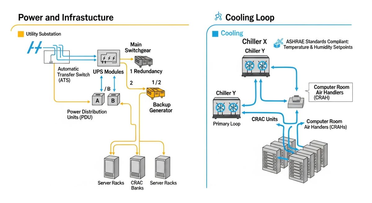
When I approach the design of a modern data centre, the first priority is the power density calculation. We are seeing rack densities move from 5kW to 30kW or even 50kW per rack in AI-focused facilities. This shift necessitates a complete rethink of the electrical distribution architecture. We must adhere to NFPA 70 (NEC) standards while ensuring that the switchgear and UPS systems are sized for N+1 or 2N redundancy.
Thermal management is the second pillar. The cooling load is no longer just about ambient air temperature; it is about managing the heat flux at the chip level. In my experience, liquid cooling is becoming the standard for high-density zones. We calculate the required cooling capacity using the formula: Q = m * Cp * delta T, where Q is the heat load, m is the mass flow rate of the coolant, and Cp is the specific heat capacity. For water-based systems, we must maintain strict water quality parameters to prevent scaling and corrosion in the piping network, often referencing ASHRAE TC 9.9 guidelines.
Critical Design Limitation:
Never underestimate the impact of floor loading and vibration. High-density server racks, combined with heavy battery arrays for UPS systems, often exceed standard commercial floor load capacities. Always verify structural slab thickness and reinforcement against the specific weight of the proposed rack layout during the FEED stage.
The EPC considerations for these facilities involve a tight integration of MEP (Mechanical, Electrical, and Plumbing) services. We utilize Building Information Modeling (BIM) to perform clash detection between massive busbar runs and chilled water piping. A common failure point in my projects has been the lack of coordination between the structural steel erection and the heavy equipment rigging path. We must ensure that the facility design allows for the replacement of large components like chillers or transformers without requiring structural demolition.
Finally, we must address the fire protection systems. Traditional water-based sprinklers are often insufficient or dangerous for high-value server environments. We typically implement gaseous fire suppression systems, such as FM-200 or Novec 1230, which are designed to extinguish fires without damaging sensitive electronic equipment. These systems require airtight room integrity testing, which must be factored into the construction schedule as a critical path activity.
Modern Data Centre Infrastructure: A comparative analysis of high-availability design strategies and their associated operational trade-offs in large-scale EPC projects.
Advantages
- Enhanced Uptime: Tier IV designs provide fault-tolerant infrastructure, ensuring 99.995% availability.
- Scalability: Modular EPC approaches allow for “pay-as-you-grow” capacity expansion.
- Energy Efficiency: Advanced economizers and liquid cooling significantly lower PUE ratios.
- Security: Integrated physical and logical security layers protect critical data assets.
Disadvantages
- High Capital Expenditure: Redundant systems and specialized cooling drive up initial project costs.
- Complexity: Managing multi-vendor MEP systems requires highly skilled facility operations teams.
- Regulatory Hurdles: Stringent environmental and fire safety codes can delay permitting timelines.
- Maintenance Intensity: High-availability systems require frequent, rigorous testing and component replacement.
Data Centre Deployment Scenarios: Specialized engineering configurations tailored to meet the unique operational requirements of diverse industrial and commercial sectors.
Hyperscale Cloud Infrastructure
These facilities are designed for massive scale and rapid deployment, utilizing standardized, repeatable building blocks. The engineering focus is on optimizing power distribution efficiency and minimizing the time-to-market through pre-fabricated modular components.
High-Performance Computing (HPC) Centres
HPC environments require extreme power densities and advanced liquid cooling solutions to support AI and machine learning workloads. The design must prioritize low-latency connectivity and high-capacity thermal rejection systems to prevent thermal throttling of high-end processors.
Edge Computing Facilities
Located closer to the end-user, these smaller, distributed data centres require robust, self-contained cooling and power systems. The engineering challenge lies in maintaining high reliability in non-traditional environments with limited physical security and maintenance access.
Financial Services Data Centres
These facilities demand the highest levels of physical and logical security, often exceeding standard Tier IV requirements. Engineering designs incorporate multi-layered redundancy for all critical systems, including dual-path power feeds and advanced seismic bracing for all equipment racks.
In my two decades of managing EPC projects, I have found that the foundation of a high-availability facility rests on the precise alignment of mechanical and electrical design parameters. The following table outlines the standard operating ranges and design thresholds that govern the performance of a modern data centre, ensuring compliance with Uptime Institute Tier III and IV requirements.
These values represent the baseline for equipment selection and thermal management strategies. Engineers must account for site-specific ambient conditions and altitude derating factors when applying these metrics to their specific project load profiles.
| Parameter | Standard Range | Reference Standard |
|---|---|---|
| Server Inlet Temperature | 18 to 27 degrees Celsius | ASHRAE TC 9.9 |
| Relative Humidity | 40 to 60 percent | ASHRAE TC 9.9 |
| Power Factor | 0.95 to 1.0 (Lagging) | IEEE 519 |
| Floor Loading | 12 to 20 kN per square meter | ASCE 7 |
Adhering to these ranges minimizes the risk of hardware failure and optimizes the Power Usage Effectiveness (PUE) of the facility. Always verify that your cooling plant capacity includes sufficient N+1 or 2N redundancy to maintain these parameters during peak demand cycles.
The complexity of modern data centre engineering requires a rigorous mapping of physical assets to their respective regulatory and performance frameworks. This matrix serves as a cross-reference tool for project managers and lead engineers to ensure that every subsystem, from the medium voltage switchgear to the fire suppression gas, meets the necessary safety and operational certifications.
By standardizing these entities, we reduce the risk of integration errors during the commissioning phase. Each entry below links to the governing body or standard that dictates the installation and maintenance protocols for that specific component class.
| System Entity | Primary Standard | Key Metric |
|---|---|---|
| UPS Systems | IEC 62040 | Efficiency/Autonomy |
| Fire Suppression | NFPA 75 | Discharge Time |
| HVAC/Chillers | AHRI 550/590 | kW per Ton |
| Grounding/Bonding | TIA-607-C | Resistance (Ohms) |
This matrix should be updated throughout the project lifecycle as new equipment specifications are finalized. It acts as a single source of truth for the engineering team, ensuring that all procurement and installation activities remain aligned with the initial design intent and safety requirements.
In my experience, the transition from construction to operation is where most projects face critical failure points. A structured verification process is mandatory to ensure that the facility meets its design availability targets. This checklist focuses on the final pre-commissioning phase, ensuring that all systems are integrated and tested under load.
-
Electrical Continuity: Verify all grounding paths meet TIA-607-C standards for resistance and bonding integrity. -
Thermal Load Testing: Conduct a full-scale heat load test using dummy racks to validate cooling capacity under peak conditions. -
Fire Suppression Integrity: Perform a room integrity test to ensure the enclosure can maintain the required concentration of suppression gas. -
BMS Integration: Confirm all sensors, including leak detection and environmental monitors, report accurately to the central Building Management System. -
Redundancy Verification: Simulate a utility power failure to ensure the Automatic Transfer Switch (ATS) and UPS systems engage within the specified millisecond window.
Each item on this list must be signed off by the lead engineer and the commissioning agent. Do not bypass these steps, as the cost of retrofitting a live data centre is exponentially higher than addressing these issues during the construction phase. Always maintain a detailed log of all test results for future audit and maintenance planning.
The Problem: Thermal Stratification and Hot Spots
During the commissioning of a 5MW facility, we identified significant thermal stratification in the server hall, leading to localized hot spots exceeding 35 degrees Celsius.
- Improper placement of perforated floor tiles relative to high-density racks.
- Airflow bypass through cable cutouts in the raised floor system.
- Inadequate pressure differential between the cold aisle and the hot aisle.
- Misalignment of CRAC unit discharge air with the server intake requirements.
The Outcome: Optimized Airflow Management
By implementing a comprehensive containment strategy and adjusting the floor tile configuration, we successfully stabilized the environment.
- Reduced average server inlet temperature by 8 degrees Celsius.
- Achieved a 15 percent improvement in overall cooling system efficiency.
- Eliminated all identified hot spots within the server hall.
- Extended the lifespan of critical IT hardware by maintaining stable thermal conditions.
My recommendation for similar projects is to prioritize Computational Fluid Dynamics (CFD) modeling during the design phase. This allows for the identification of potential airflow issues before the physical installation, saving significant time and capital during the commissioning process.
What are the primary differences between N+1 and 2N redundancy?
N+1 redundancy provides one additional component for every N required components, ensuring that the system can survive a single failure. In contrast, 2N redundancy provides a completely mirrored system, offering two independent power paths from the utility to the server rack.
- N+1 is cost-effective but leaves the system vulnerable during maintenance of the shared bus.
- 2N provides concurrent maintainability and fault tolerance, which is the gold standard for Tier IV facilities.
- The choice depends on the business’s tolerance for downtime and the specific SLA requirements of the end-users.
How does ASHRAE TC 9.9 impact cooling system design?
The ASHRAE TC 9.9 guidelines define the environmental envelopes for IT equipment, allowing for higher operating temperatures than traditional standards. This shift enables engineers to utilize free cooling and economizers more effectively.
- Higher inlet temperatures reduce the reliance on mechanical refrigeration.
- Strict humidity control remains necessary to prevent electrostatic discharge and corrosion.
- Designers must balance energy savings with the potential impact on hardware reliability and warranty terms.
Why is fire suppression gas selection critical for data centres?
Data centres require clean agent fire suppression systems that do not leave residue or damage sensitive electronic components. Water-based systems are generally avoided in the server hall due to the risk of short circuits and permanent hardware damage.
- Inert gases and chemical agents like FM-200 or Novec 1230 are industry standards.
- The system must be designed to maintain the required concentration for a specific hold time.
- Compliance with NFPA 75 is mandatory for the protection of information technology equipment.
What role does the Building Management System (BMS) play?
The BMS acts as the central nervous system of the data centre, integrating mechanical, electrical, and security subsystems into a single monitoring platform. It provides real-time visibility into power consumption, thermal conditions, and equipment health.
- Automated alerts allow for proactive maintenance before a component failure occurs.
- Data logging is essential for capacity planning and PUE reporting.
- Integration with the Data Centre Infrastructure Management (DCIM) software provides a holistic view of facility operations.
How do you manage harmonic distortion in power distribution?
Modern data centres utilize high-frequency switching power supplies that can introduce significant harmonic distortion into the electrical grid. This can lead to overheating of transformers and neutral conductors if not properly mitigated.
- Active harmonic filters are often installed at the main distribution boards.
- Oversizing neutral conductors is a common design practice to handle non-linear load currents.
- Compliance with IEEE 519 standards is the benchmark for maintaining power quality.
What are the key considerations for site selection?
Site selection is a multi-faceted decision involving power availability, network connectivity, and environmental risk assessment. Proximity to major fiber backbones and reliable, redundant utility power feeds is non-negotiable.
- Assess seismic activity and flood risk to ensure long-term facility viability.
- Evaluate the cost and availability of renewable energy sources to meet sustainability goals.
- Consider local zoning laws and the potential for future expansion of the facility footprint.
Complete Course on
Piping Engineering
Check Now
Key Features
- 125+ Hours Content
- 500+ Recorded Lectures
- 20+ Years Exp.
- Lifetime Access
Coverage
- Codes & Standards
- Layouts & Design
- Material Eng.
- Stress Analysis

📚 Recommended Resources: Modern Data Centre
Read these Guides
- 📄 Optimizing Data Centre Energy Efficiency and PUE Calculation Standards
- 📄 Renewable Energy for Data Centres: Engineering Sustainable Infrastructure Solutions
- 📄 Battery Energy Storage Systems for Data Centres: Engineering Design Guide
- 📄 Liquid Cooling for AI Data Centres: Engineering High-Density Thermal Solutions