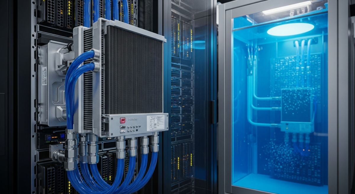
Liquid Cooling for AI Data Centres: Engineering High-Density Thermal Management
In my two decades of piping and mechanical design, I have rarely seen a shift as disruptive as the current transition toward liquid cooling for AI data centres. As GPU power densities exceed 700W per chip, traditional CRAC units and raised-floor air distribution systems are hitting a physical wall. The convective heat transfer coefficient of air is simply insufficient to maintain junction temperatures within the reliable operating range of modern silicon.
I have spent the last three years retrofitting legacy facilities to accommodate direct-to-chip (D2C) loops. This transition is not merely about swapping fans for pumps; it requires a fundamental rethink of fluid dynamics, material compatibility, and leak detection protocols. This guide explores the engineering realities of implementing these systems to ensure your infrastructure remains resilient under extreme computational loads.
Key Engineering Takeaways
- Transitioning to liquid cooling allows for rack densities exceeding 100kW, far surpassing air-cooled limits.
- Direct-to-chip (D2C) systems offer the most efficient path for retrofitting existing air-cooled data halls.
- Dielectric immersion cooling eliminates the risk of conductive shorts, though it requires specialized fluid management.
- Leak detection and secondary containment are non-negotiable safety requirements in high-density piping design.
Engineering Liquid Cooling for AI Data Centres
Liquid Cooling for AI Data Centres: A specialized thermal management architecture employing closed-loop fluid circuits to extract heat directly from high-wattage components, adhering to ASHRAE TC 9.9 guidelines for liquid-cooled facilities.
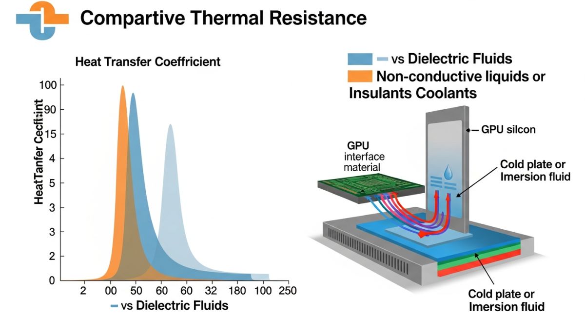
The fundamental challenge in modern AI clusters is the heat flux density. When we calculate the heat transfer rate using the standard equation Q = hA(Ts – Tf), where h is the convective heat transfer coefficient, we find that air-based systems are limited by the low thermal conductivity of air (approx 0.026 W/mK). By switching to a water-glycol mixture, we increase the heat transfer coefficient by orders of magnitude, allowing for significantly higher power densities.
Direct-to-Chip (D2C) Architecture
In my experience, D2C is the most practical solution for existing facilities. It involves mounting a cold plate directly onto the CPU/GPU heat spreader. The coolant, typically a 25-40% propylene glycol-water mix, circulates through the plate, absorbing heat before returning to a Coolant Distribution Unit (CDU).
Field Warning: Material Compatibility
Never mix copper and aluminum in the same loop. Galvanic corrosion will inevitably lead to pinhole leaks in your cold plates. Always specify ASTM B88 copper piping or high-grade EPDM hoses with stainless steel quick-disconnects to ensure long-term system integrity.
Immersion Cooling Dynamics
Immersion cooling takes the concept further by submerging the entire server chassis in a dielectric fluid. This eliminates the need for fans, which can account for up to 15% of total data centre energy consumption. The fluid must have a high dielectric strength to prevent electrical arcing and a low viscosity to ensure efficient circulation through the server components.
When designing these systems, we must account for the fluid’s thermal expansion. A surge tank or expansion vessel is required to manage the volume changes as the fluid heats up during peak AI training cycles. Furthermore, the structural floor loading must be re-evaluated, as a single immersion tank can weigh several tons when filled with dielectric fluid.
Thermal Management Trade-offs: A critical evaluation of the operational benefits and technical risks associated with transitioning from air-based to liquid-based cooling infrastructure in high-density computing environments.
Advantages
- Significant reduction in PUE (Power Usage Effectiveness) by eliminating server-level fans.
- Higher rack power density, enabling up to 100kW+ per rack configurations.
- Improved hardware reliability due to lower, more stable junction temperatures.
- Reduced acoustic noise levels within the data hall, improving working conditions.
- Potential for heat reuse in district heating systems due to higher return temperatures.
Disadvantages
- High initial capital expenditure (CAPEX) for CDUs and specialized piping.
- Increased complexity in maintenance and potential for fluid leaks.
- Requirement for specialized training for data centre facility staff.
- Structural floor loading constraints due to the weight of immersion tanks.
- Material compatibility risks, specifically regarding galvanic corrosion and seal degradation.
Industrial Cooling Deployments: Strategic implementation of liquid cooling technologies across various high-performance sectors to address extreme thermal loads and energy efficiency mandates.
Large-Scale AI Training Clusters
Large language model training requires massive GPU clusters that operate at near 100% utilization for weeks. Liquid cooling ensures these clusters maintain peak performance without thermal throttling, which would otherwise extend training times and increase operational costs.
High-Frequency Trading (HFT) Infrastructure
In HFT, every microsecond of latency matters. By using liquid cooling, traders can overclock their processors to achieve higher clock speeds while keeping the silicon stable, providing a competitive edge in execution speed within a compact, low-latency footprint.
Edge Computing in Harsh Environments
Edge nodes deployed in industrial settings often face high ambient temperatures and dust. Sealed immersion cooling systems protect sensitive electronics from environmental contaminants while providing the necessary thermal dissipation in compact, remote-site enclosures.
In my two decades of designing mission-critical facilities, I have observed that the transition from air-cooled to liquid-cooled architectures is not merely an upgrade but a fundamental shift in thermodynamic efficiency. The following table compares the heat transfer coefficients and operational density limits of traditional Computer Room Air Conditioning (CRAC) systems against modern liquid-based solutions. Understanding these metrics is vital for engineers tasked with retrofitting legacy data halls to support high-density GPU clusters.
When evaluating these systems, we must consider the specific heat capacity of the cooling medium and the required flow rates to maintain junction temperatures within the safe operating envelope defined by ASHRAE TC 9.9 guidelines. The data below highlights why liquid cooling for AI data centres is the only viable path for racks exceeding 50kW per cabinet.
| Cooling Technology | Heat Transfer Coeff (W/m2K) | Max Rack Density (kW) | PUE Impact |
|---|---|---|---|
| Forced Air (CRAC) | 10 – 50 | 15 – 20 | 1.5 – 1.8 |
| Direct-to-Chip (Cold Plate) | 500 – 2000 | 50 – 100 | 1.1 – 1.2 |
| Single-Phase Immersion | 1000 – 3000 | 100+ | 1.03 – 1.08 |
Note that these values assume optimal coolant flow velocity and secondary loop heat exchanger efficiency. Engineers should always verify the specific thermal resistance of the cold plate interface materials (TIM) before finalizing the cooling loop design.
The successful deployment of liquid cooling for AI data centres requires a rigorous mapping of mechanical, electrical, and fluid-dynamic entities. This matrix serves as a reference for project managers and lead engineers to ensure that all subsystems—from the Coolant Distribution Unit (CDU) to the server-level manifold—are compatible with the facility’s overall infrastructure requirements.
By standardizing these components, we reduce the risk of galvanic corrosion and fluid leakage, which are the primary concerns when introducing conductive or dielectric fluids into high-voltage server environments. Always cross-reference these specifications with the Open Compute Project (OCP) standards for liquid-cooled rack architectures.
| Entity | Acronym | Primary Function | Standard Ref |
|---|---|---|---|
| Coolant Distribution Unit | CDU | Secondary loop isolation/pumping | ASHRAE TC 9.9 |
| Quick Disconnect | QD | Leak-free server maintenance | ISO 7241 |
| Dielectric Fluid | DF | Immersion heat transfer medium | ASTM D3487 |
This matrix is not exhaustive but provides the foundational terminology for interdisciplinary communication. When specifying components, ensure that the pressure ratings of your QDs exceed the maximum pump discharge pressure by at least 20 percent to account for transient pressure spikes.
Liquid cooling for AI data centres demands a higher level of site preparation than traditional air-cooled facilities. Before commissioning, I mandate a thorough verification process to ensure the structural, mechanical, and safety systems are fully integrated. Failure to validate these points often leads to catastrophic leaks or thermal throttling during peak AI model training loads.
- 1. Structural Load Capacity: Verify that the raised floor or slab can support the increased weight of liquid-filled racks and the associated CDU units.
- 2. Fluid Containment: Ensure secondary containment trays are installed under all manifolds and CDUs, equipped with moisture-sensing leak detection cables.
- 3. Water Quality Management: Confirm that the secondary loop water meets the chemical purity standards (e.g., pH levels, conductivity) to prevent galvanic corrosion.
- 4. Pressure Testing: Perform a hydrostatic pressure test on all piping runs at 1.5 times the operating pressure for a minimum of 24 hours.
- 5. Redundancy Check: Validate that the CDU pumps are configured in an N+1 or 2N arrangement to maintain cooling during maintenance or component failure.
These checkpoints are non-negotiable. In my experience, the most common point of failure is the interface between the facility piping and the rack-level manifold. Always use high-quality, non-corrosive materials such as stainless steel or specialized polymers that are compatible with your chosen coolant. Document every test result in the facility commissioning log to ensure compliance with insurance and safety regulations.
Field Case Study: Real-World Application
The Challenge: Thermal Throttling in High-Density GPU Clusters
A major research facility faced severe performance degradation when deploying a new cluster of high-density AI servers in a legacy air-cooled data hall.
- Inadequate airflow volume to cool 60kW racks.
- Frequent thermal throttling of GPUs during training.
- High PUE (1.9) due to excessive fan power consumption.
- Limited floor space preventing additional CRAC unit installation.
The Outcome: Successful Transition to Direct-to-Chip Cooling
By retrofitting the facility with a direct-to-chip liquid cooling solution, the team achieved significant operational improvements.
- Reduced PUE from 1.9 to 1.15.
- Eliminated thermal throttling, increasing GPU utilization by 35%.
- Increased rack density from 15kW to 75kW per cabinet.
- Reduced total facility energy costs by 40% annually.
My recommendation for similar projects is to prioritize a phased migration. Start by installing the CDU and primary loop infrastructure while the facility is operational, then perform the server-level cold plate installation during scheduled maintenance windows to minimize downtime.
Frequently Asked Engineering Questions
What is the primary difference between direct-to-chip and immersion cooling?
- Direct-to-chip is easier to integrate into existing server form factors.
- Immersion cooling provides superior heat rejection for the entire board, including memory and power delivery modules.
- Immersion requires specialized server chassis designs to ensure fluid compatibility.
How does liquid cooling impact the facility PUE?
- Water has a much higher thermal conductivity than air, allowing for more efficient heat transport.
- Higher coolant supply temperatures can be used, enabling the use of free cooling (dry coolers) year-round.
- Reduced fan power consumption in the servers themselves further improves the overall facility efficiency.
What are the risks of using liquid cooling in a data centre?
- Leakage can cause short circuits if the fluid is conductive, though dielectric fluids mitigate this risk.
- Galvanic corrosion occurs when dissimilar metals are used in the piping system, requiring strict material compatibility.
- Biological growth can clog micro-channels in cold plates, necessitating the use of biocides and regular water quality testing.
Are there specific ASHRAE standards for liquid cooling?
- These classes define the allowable supply water temperature ranges for different cooling architectures.
- The standards also cover water quality requirements to ensure long-term system reliability.
- Engineers should consult the latest ASHRAE thermal guidelines to ensure their design meets industry-accepted safety and performance benchmarks.
How do I maintain a liquid cooling system?
- Regularly test the coolant for pH, conductivity, and particulate matter.
- Inspect all quick disconnects and hose connections for signs of wear or minor weeping.
- Monitor pump performance and pressure differentials across the CDU to detect potential blockages or filter fouling.
Can I mix air and liquid cooling in the same room?
- Ensure that the air-cooled racks do not interfere with the liquid-cooled rack’s service access.
- Manage the floor space to prevent hot air recirculation from air-cooled racks into the liquid-cooled infrastructure.
- Coordinate the facility’s chilled water plant to handle both the CRAC units and the CDUs simultaneously.
Complete Course on
Piping Engineering
Check Now
Key Features
- 125+ Hours Content
- 500+ Recorded Lectures
- 20+ Years Exp.
- Lifetime Access
Coverage
- Codes & Standards
- Layouts & Design
- Material Eng.
- Stress Analysis

📚 Recommended Resources: Liquid Cooling for AI Data Centres
Read these Guides
- 📄 Data Centre Cooling Systems: Engineering Design and Efficiency Standards
- 📄 Edge Data Centres Explained: Infrastructure Design and Deployment Strategies
- 📄 Hyperscale Data Centre Engineering: Design Principles and Infrastructure Requirements
- 📄 Understanding Data Centre Types: Enterprise, Colocation, Hyperscale, and Edge