Table of Contents
What is Metallic Piping: Types, Advantages, Applications, and ASTM Standards
In my 20 plus years of field experience managing piping stress analysis and mechanical integrity programs, I have watched materials science evolve rapidly. Yet, despite the rise of advanced composites and high-performance plastics, metallic piping remains the undisputed backbone of heavy industrial plants. When you are dealing with superheated steam at 540 degrees Celsius or volatile hydrocarbons pressurized to 150 bar, non-metallic alternatives simply cannot survive.
I remember a critical refinery expansion project where a junior engineer suggested using reinforced thermosetting resin pipes for a high-temperature utility line to save on material costs. While the initial cost savings looked attractive on paper, a quick look at the thermal expansion coefficients and pressure-temperature derating curves proved that only a robust metallic piping system could guarantee safe, long-term operation. In this guide, I will break down the core classifications, design calculations, and ASTM standards that define industrial metallic piping systems.
Key Engineering Takeaways
- Understand the critical differences between ferrous and non-ferrous metallic piping systems.
- Master the application of Barlow’s Formula for pressure design thickness under ASME B31.3.
- Identify the correct ASTM material specifications for carbon steel, stainless steel, and alloy steel.
- Learn how to prevent common field failures like galvanic corrosion and thermal stress cracking.
Complete Course on
Piping Engineering
Check Now
Key Features
- 125+ Hours Content
- 500+ Recorded Lectures
- 20+ Years Exp.
- Lifetime Access
Coverage
- Codes & Standards
- Layouts & Design
- Material Eng.
- Stress Analysis
Why Choose Metallic Piping for Industrial Plants?
When selecting materials for industrial fluid transport, we classify metallic piping into two primary categories: ferrous and non-ferrous. Ferrous piping, which contains iron as the primary constituent, includes carbon steel, stainless steel, and alloy steels. Non-ferrous piping includes copper, nickel, aluminum, and titanium alloys. Each material group serves a distinct operational window defined by temperature, pressure, and chemical compatibility.
1. Carbon Steel (The Workhorse)
Carbon steel is the most widely used material in industrial piping due to its high tensile strength, excellent weldability, and cost-effectiveness. Standard specifications like ASTM A106 Grade B are the default choice for non-corrosive utility lines, steam distribution, and hydrocarbon transport. However, carbon steel is susceptible to atmospheric and process-side corrosion, requiring corrosion allowances (typically 1.5 mm to 3.0 mm) in wall thickness calculations.
2. Stainless Steel (Corrosion Resistance)
When process fluids are corrosive or when product purity is paramount, stainless steel is required. Austenitic stainless steels, such as ASTM A312 TP304L and TP316L, contain chromium and nickel, which form a passive chromium oxide layer that prevents oxidation. The “L” designation signifies low carbon content (less than 0.03 percent), which prevents carbide precipitation during welding and maintains corrosion resistance in the heat-affected zone.
3. Alloy Steel (High-Temperature Strength)
In high-temperature power piping governed by ASME B31.1, standard carbon steel loses its mechanical strength and becomes susceptible to creep deformation. Alloy steels containing chromium and molybdenum (such as ASTM A335 P11, P22, and P91) are engineered to withstand temperatures exceeding 500 degrees Celsius. Chromium provides oxidation resistance, while molybdenum increases creep strength and high-temperature tensile properties.
In my years of troubleshooting piping failures, I have frequently observed severe localized corrosion at the interface where copper piping connects directly to carbon steel piping. This is classic galvanic corrosion. When dissimilar metals are in electrical contact in the presence of an electrolyte, the more active metal (carbon steel) corrodes rapidly. Always install a dielectric isolation union or a non-conductive gasket kit to isolate these materials.
Pressure Design and Wall Thickness Calculations
To ensure a metallic pipe can safely contain internal pressure, we must calculate its minimum required wall thickness. Under ASME B31.3 Section 304.1.2, the basic formula for the pressure design thickness (t) of straight pipe under internal pressure is:
Where:
- P = Internal design gage pressure (psi or MPa)
- D = Outside diameter of the pipe (inches or mm)
- S = Allowable stress value for the material at design temperature from ASME B31.3 Table A-1 (psi or MPa)
- E = Quality factor (1.0 for seamless pipe, 0.85 for electric resistance welded pipe)
- W = Weld joint strength reduction factor (1.0 for typical temperatures)
- Y = Coefficient from Table 304.1.1 (0.4 for ductile metals at temperatures below 482 degrees Celsius)
Once the pressure design thickness (t) is calculated, you must add mechanical allowances (such as thread depth or groove depth), corrosion allowances (c), and account for the manufacturer’s mill tolerance (typically 12.5 percent for seamless pipe) to determine the nominal wall thickness.
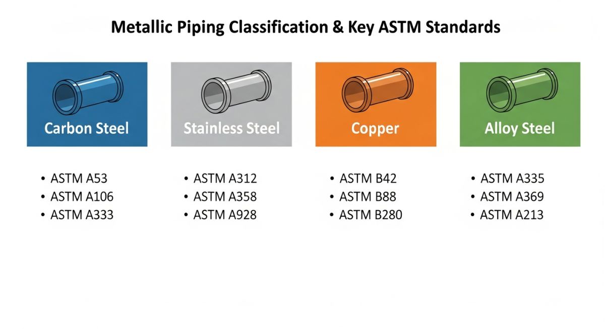
How to Select Metallic Piping ASTM Specifications
Specifying the correct ASTM standard is critical to ensuring that the piping materials delivered to your job site match the design assumptions made during stress analysis. Below is a curated reference table of the most common ASTM standards used in industrial metallic piping systems.
| ASTM Standard | Material Group | Common Application | Temperature Range |
|---|---|---|---|
| ASTM A106 | Carbon Steel (Seamless) | High-temperature, high-pressure hydrocarbon and steam lines | -29 to 425 °C |
| ASTM A333 | Carbon Steel (Low-Temp) | Cryogenic and low-temperature process piping | -45 to 343 °C |
| ASTM A312 | Stainless Steel (Seamless/Welded) | Corrosive chemical processing and food-grade systems | -254 to 815 °C |
| ASTM A335 | Alloy Steel (Seamless) | Superheated steam lines in power generation plants | Up to 650 °C |
| ASTM B88 | Copper (Seamless) | Domestic water distribution and HVAC refrigerant lines | -196 to 204 °C |
Technical Mapping & Specifications Matrix
To bridge the gap between design codes and physical procurement, engineers must map key physical parameters to their corresponding industry acronyms and standards.
| Entity / Acronym | Physical Parameter | Standard Reference | Engineering Significance |
|---|---|---|---|
| NPS | Nominal Pipe Size | ASME B36.10M | Standardizes the dimensionless designator for pipe diameter. |
| SCH | Pipe Schedule | ASME B36.19M | Defines the wall thickness relative to the pipe diameter. |
| Sy | Yield Strength | ASME Section II Part D | The stress limit where plastic deformation begins. |
| PREN | Pitting Resistance Equivalent Number | ASTM G48 | Quantifies pitting corrosion resistance of stainless steels. |
Field Inspection Checklist for Metallic Piping
Before any metallic piping system is pressurized and put into service, a rigorous field inspection must be performed. Skipping these steps can lead to catastrophic failures during hydrotesting or, worse, during plant startup. Use this checklist on your job site to ensure compliance with engineering designs.
Pre-Hydrotest Verification Checklist
-
Material Traceability (MTRs): Verify that all pipe spools, fittings, and flanges have visible heat numbers that match the Mill Test Reports.
-
Weld Joint Alignment: Ensure fit-up alignment (internal misalignment or “high-low”) does not exceed 1.5 mm as specified by ASME B31.3.
-
Support and Hanger Placement: Confirm that all spring hangers, guides, and anchors are installed in their exact isometric locations and that travel stops are removed from spring supports.
-
Nondestructive Examination (NDE): Confirm that all required radiography (RT), ultrasonic testing (UT), or dye penetrant testing (PT) has been completed and approved.
-
Flange Bolt Torquing: Verify that flange bolts are lubricated and torqued in a star pattern to the specified torque values using calibrated torque wrenches.
Field Case Study: Real-World Application
The Problem: Thermal Fatigue Failure
At a combined cycle power plant, a 12-inch superheated steam line operating at 480 degrees Celsius and 85 bar experienced a catastrophic weld failure at a 90-degree elbow. The line was constructed using standard carbon steel (ASTM A106 Gr. B) instead of the specified alloy steel (ASTM A335 P22).
In addition to the incorrect material specification, the piping stress analysis had not accounted for the restriction of thermal expansion caused by a newly installed structural steel platform. The pipe was physically binding against the structural steel, preventing the natural thermal growth of the loop and generating massive bending moments at the elbow weld joint.
The Outcome: Engineering Rectification
I was brought in to lead the root cause analysis. We immediately cut out the failed section and performed Positive Material Identification (PMI) on the remaining piping, confirming the material mix-up. The entire run was replaced with ASTM A335 P22 alloy steel to handle the high-temperature creep regime.
We remodeled the piping system in CAESAR II stress analysis software, modified the structural steel platform to provide a 150 mm clearance envelope, and redesigned the pipe guides. The system was successfully hydrotested at 1.5 times the design pressure and has operated without incident for over five years.
My recommendation for any high-temperature piping project is simple: never rely solely on paper documentation. Implement a mandatory PMI program for all alloy steel components prior to welding, and always perform a final walkdown of the piping system in its hot operating condition to verify clearances.
Frequently Asked Engineering Questions
What is the difference between ASTM A106 and ASTM A53 pipe?
How does temperature affect the allowable stress of metallic piping?
Why is low carbon stainless steel (e.g., 316L) preferred for welding?
What is the purpose of a corrosion allowance in piping design?
How do you calculate the test pressure for a hydrotest?
When should you use seamless vs. welded metallic piping?

📚 Recommended Resources: metallic piping
Read these Guides
🎓 Advanced Training


Related posts:
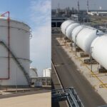
![Industrial gas processing facility comparing cryogenic LNG storage tanks and pressurized LPG bullet tanks.]()
What are the Differences Between LNG and LPG?
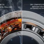
![Split-screen comparison of liquid oil failing under extreme heat versus dry graphite lubricating a mechanical bearing smoothly.]()
Why Is Graphite a Better Lubricant Than Oil in Industrial Piping?
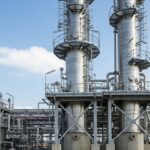
![Tall industrial distillation column tower at a chemical processing plant]()
What is a Distillation Column? Working Principles and Types
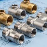
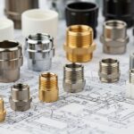
![Close-up of various metal pipe fittings with different thread types on an engineering blueprint.]()
Understanding the Different Types of Pipe Threads in Piping Systems
![A collection of different metal and plastic pipe ferrules resting on an engineering blueprint.]()
How Do Pipe Ferrules Ensure Leak-Free Industrial Piping Systems?
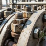
![Close-up of heavy-duty industrial piping fasteners securing a steel flange joint.]()
Piping Fasteners: Engineering Selection, Torque Calculations, and Installation Standards