Table of Contents
What is Metal Fatigue and How Do Engineers Prevent It?
In my 20 years of troubleshooting piping systems, pressure vessels, and rotating machinery, I have seen some of the most catastrophic failures occur without a single warning sign. No visible yielding, no necking, and no prior deformation. The culprit is almost always metal fatigue. It is a silent killer of industrial infrastructure. A component can operate perfectly under a specific load for years, only to snap suddenly because that load cycled millions of times.
Understanding how fatigue initiates and propagates is not just an academic exercise; it is a core requirement for plant safety and reliability. When we design piping systems under ASME B31.3, we must account for thermal expansion cycles that induce cyclic displacement stresses. If we ignore these cyclic stresses, the system will inevitably fail long before its intended design life.
Key Engineering Takeaways
- Fatigue failures occur at stress levels significantly lower than the material’s yield strength.
- Sharp corners, weld defects, and corrosion pits act as severe stress concentrators that accelerate crack initiation.
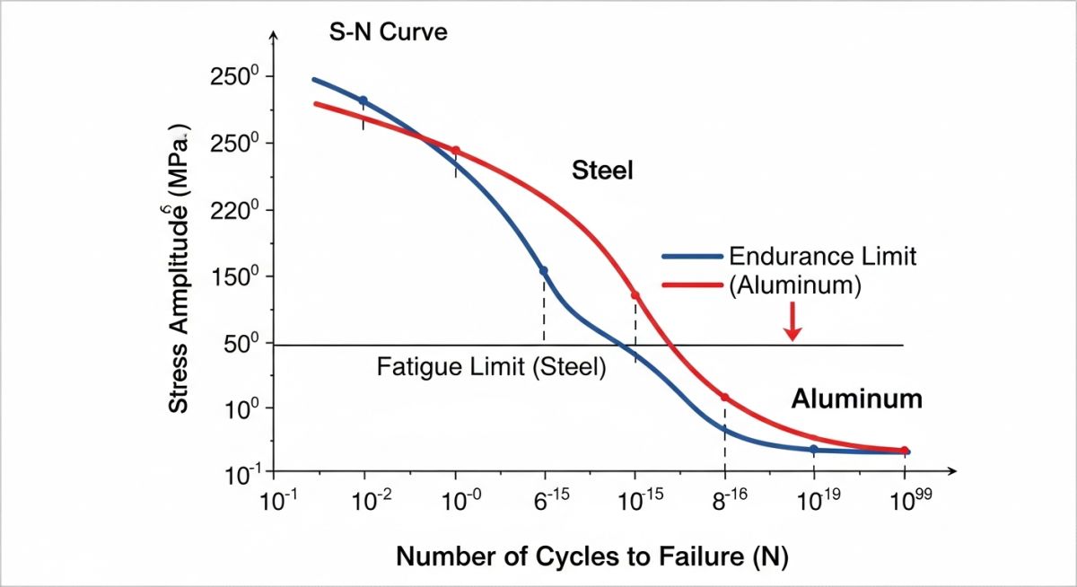
- The S-N curve is the primary tool used to determine the fatigue life of a component under specific cyclic stress amplitudes.
- Non-destructive testing (NDT) methods like dye penetrant and magnetic particle testing are required to detect surface-breaking fatigue cracks early.
How Does Metal Fatigue Cause Catastrophic Structural Failures?
To truly understand metal fatigue, we must look at the microstructural level. Under cyclic loading, localized plastic deformation occurs even if the nominal stress remains well within the elastic regime. This localized slip leads to the formation of microscopic intrusions and extrusions on the material’s surface. These surface disruptions act as microscopic notches where stress concentrates, initiating the first micro-cracks.
The Three Stages of Fatigue Degradation
I always explain fatigue to junior engineers as a three-stage process. Each stage has distinct physical characteristics that we can identify during post-failure forensic analysis:
- Stage I (Crack Initiation): Micro-cracks initiate along crystallographic slip planes where shear stresses are highest. This stage is highly sensitive to surface finish, weld profiles, and environmental factors.
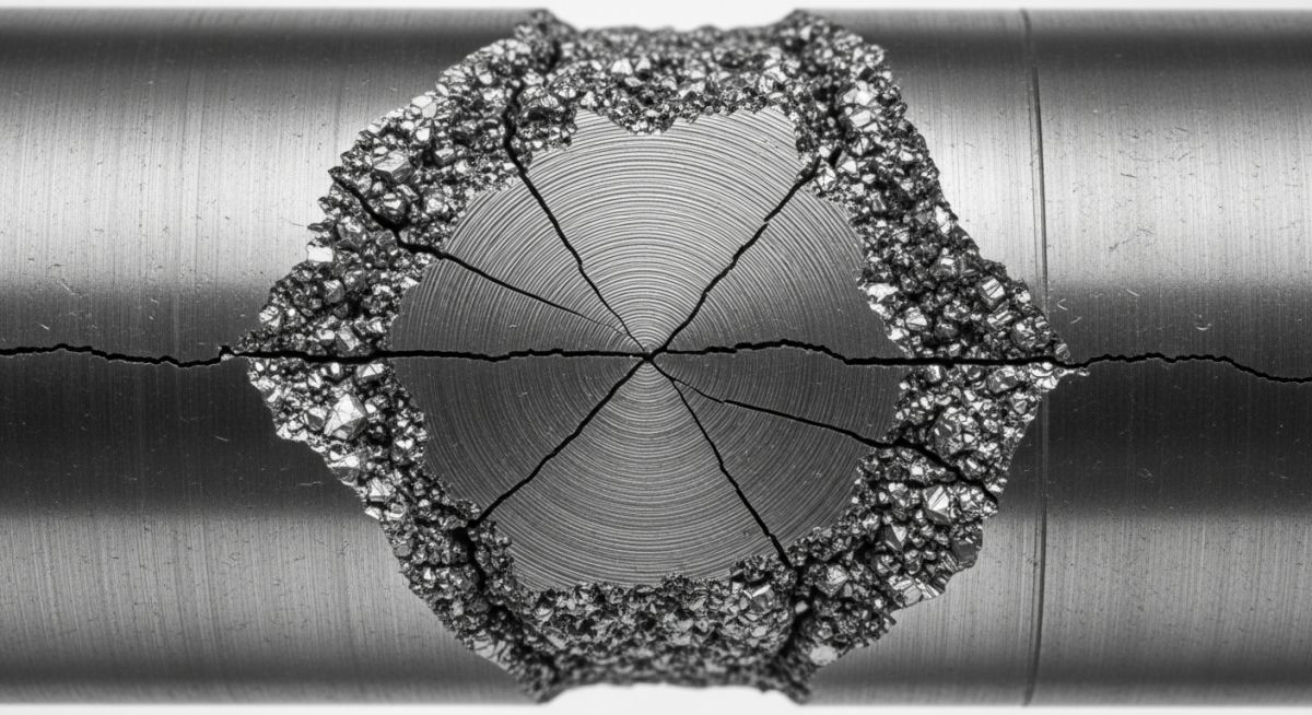
- Stage II (Crack Propagation): The crack begins to propagate perpendicular to the direction of the tensile stress. As the crack opens and closes with each cycle, it leaves behind microscopic ridges known as “striations.” On a macroscopic scale, these appear as “beach marks” or “concentric rings” radiating from the initiation point.
- Stage III (Fast Fracture): The load-bearing cross-sectional area of the component decreases as the crack grows. Eventually, the remaining metal can no longer support the peak load, resulting in sudden, catastrophic brittle fracture.
Never assume a system operating below its yield strength is safe from fatigue. In my experience, over 80% of mechanical failures in operating plants are caused by fatigue, often driven by high-frequency acoustic vibrations or thermal cycling that were completely overlooked during the initial static design phase.
Mathematical Determination of Fatigue Life
To calculate the fatigue life of a component, we rely on empirical relationships. For high-cycle fatigue (where nominal stresses are elastic), we use Basquin’s Equation to relate stress amplitude to the number of cycles to failure:
Where:
• Sa is the alternating stress amplitude.
• Sf’ is the fatigue strength coefficient (approximately equal to the true fracture strength).
• Nf is the number of cycles to failure.
• b is the fatigue strength exponent (typically ranging from -0.05 to -0.12 for metals).
For crack propagation rates, we apply Paris’ Law, which allows us to estimate the remaining useful life of a component once a crack has been detected:
Where da/dN is the crack growth rate per cycle, Delta K is the range of the stress intensity factor, and C and m are material constants determined experimentally under ASTM E647.
What Materials Best Resist Metal Fatigue Under Cyclic Stress?
When selecting materials for cyclic service, we must distinguish between ferrous and non-ferrous alloys. Ferrous metals, such as carbon steels and titanium alloys, exhibit a distinct “endurance limit.” Below this stress level, the material can theoretically withstand an infinite number of cycles without failing. Non-ferrous metals, like aluminum and copper, do not have a true endurance limit; they will eventually fail if cycled long enough, even at very low stress levels.
Fatigue Limits of Common Engineering Alloys
| Material Specification | Tensile Strength (MPa) | Yield Strength (MPa) | Fatigue Limit (MPa) | Fatigue Ratio (Limit/Tensile) |
|---|---|---|---|---|
| ASTM A36 Carbon Steel | 400 | 250 | 200 | 0.50 |
| ASTM A106 Grade B Steel | 415 | 240 | 185 | 0.45 |
| ASTM A312 TP316L Stainless | 485 | 170 | 240 | 0.49 |
| Aluminum 6061-T6 | 310 | 276 | 95 (at 5e8 cycles) | 0.31 |
| Titanium Grade 5 (Ti-6Al-4V) | 950 | 880 | 510 | 0.54 |
Technical Mapping & Specifications Matrix
| Fatigue Parameter | Acronym / Symbol | Physical Meaning | Governing Standard |
|---|---|---|---|
| Stress Intensity Factor Range | Delta K | The driving force for crack propagation per cycle. | ASTM E399 |
| Fatigue Strength Exponent | b | Slope of the elastic strain amplitude versus life curve. | ASTM E606 |
| Fatigue Limit | Se | Stress level below which infinite life is expected. | ISO 12107 |
| Stress Ratio | R | Ratio of minimum stress to maximum stress (Smin/Smax). | ASTM E466 |
How to Inspect for Metal Fatigue in the Field?
In my years managing turnaround inspections, I have established a strict protocol for identifying fatigue-prone areas. You cannot rely on visual inspection alone. By the time a fatigue crack is visible to the naked eye, the component is often near the end of its life. We must target high-risk locations like weld toes, structural attachments, and geometric transitions using advanced NDT methods.
Site Verification Checklist: Fatigue Prevention
-
Identify High-Cycle Locations: Map out all piping and structural components located near reciprocating compressors, pumps, or high-velocity flow control valves.
-
Inspect Weld Profiles: Verify that all welds in cyclic service have smooth transitions. Grinding weld toes to a smooth radius significantly reduces stress concentration factors.
-
Perform Dye Penetrant Testing (PT): Apply PT on non-magnetic materials like stainless steel to detect fine, surface-breaking cracks at high-stress joints.
-
Execute Magnetic Particle Testing (MT): Use wet fluorescent MT on carbon steel components for superior sensitivity to surface and near-surface fatigue cracks.
-
Monitor Vibration Levels: Use portable accelerometers to measure piping displacement and frequency. Compare values against ASME OM3 vibration limits.
Field Case Study: Real-World Application
The Problem: Recurrent Piping Failures at a Compressor Station
At a natural gas processing facility, a 2-inch bypass line connected to a reciprocating compressor discharge header suffered three sudden failures over an 18-month period. Each failure occurred at the weld toe of the branch connection. The plant operators initially blamed poor weld quality and re-welded the joint each time.
When I was called to investigate, I performed a vibration analysis and found that the compressor was generating high-frequency pressure pulsations at 120 Hz. This frequency matched the natural frequency of the bypass piping loop, causing resonance. The resulting cyclic bending stresses at the branch connection weld toe exceeded the fatigue limit of the ASTM A106 carbon steel pipe, leading to rapid high-cycle fatigue failure.
The Outcome: Engineering Redesign and Vibration Mitigation
Instead of simply re-welding the joint, my team implemented a permanent engineering solution:
- We replaced the standard branch connection with an integrally reinforced forged branch outlet (Weldolet) to reduce the stress concentration factor from 4.0 to 1.5.
- We installed a pulsation dampener bottle at the compressor discharge to absorb the high-frequency pressure waves.
- We added a rigid, high-frequency pipe clamp to shift the piping system’s natural frequency away from the compressor’s operating frequency.
Following these modifications, vibration levels dropped by 85%, and the piping system has operated continuously for over five years without a single fatigue crack.
This case highlights a fundamental rule of piping engineering: when a component fails due to fatigue, simply repairing it to the original design will only guarantee another failure. You must identify and eliminate the root cause of the cyclic stress.
Frequently Asked Engineering Questions
What is the difference between high-cycle and low-cycle fatigue?
How does corrosion affect the fatigue life of metals?
Can a fatigue crack be repaired by welding over it?
What is the role of shot peening in preventing metal fatigue?
How do temperature variations influence fatigue behavior?
Why do sharp corners and threads reduce fatigue life so drastically?
===FAQ_BLOCK===

Complete Course on
Piping Engineering
Check Now
Key Features
- 125+ Hours Content
- 500+ Recorded Lectures
- 20+ Years Exp.
- Lifetime Access
Coverage
- Codes & Standards
- Layouts & Design
- Material Eng.
- Stress Analysis
📚 Recommended Resources: metal fatigue
Read these Guides
🎓 Advanced Training


Related posts:
![Industrial worker welding a large structural steel I-beam in a fabrication facility.]()
What is Structural Steel Fabrication and How Does It Work?
![A heavy-duty stainless steel turnbuckle tensioning a structural cable.]()
What is a Turnbuckle and How to Install It?
![Stack of newly manufactured galvanized steel pipes in an industrial warehouse]()
Understanding the Galvanized Pipe Meaning in Modern Piping Systems
![Industrial Alloy 625 piping components in a manufacturing plant]()
What is Alloy 625? Properties, Grades, and Applications of Alloy 625
![Industrial machinery fitted with smart sensors displaying real-time condition-based maintenance data on a digital overlay.]()
What is Condition-Based Maintenance and How Does It Work?
![Comparison of high viscosity honey and low viscosity water pouring to demonstrate fluid resistance]()
Understanding Newton's Law of Viscosity and Key Fluid Flow Factors