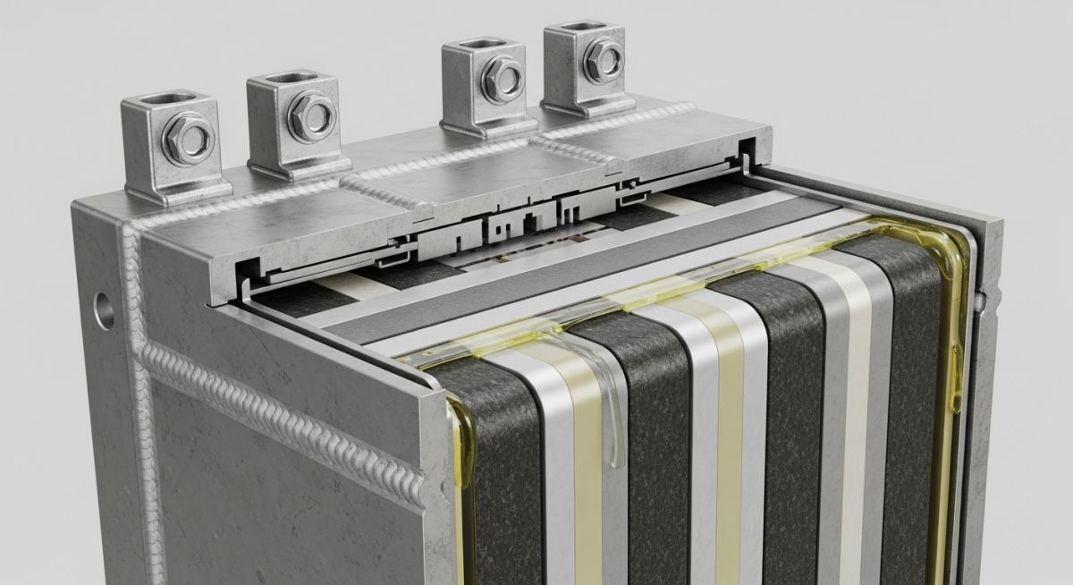
Lithium-Ion Batteries Explained for BESS Applications
In my two decades of experience managing complex industrial infrastructure, I have observed that the transition to renewable energy hinges entirely on the reliability of Battery Energy Storage Systems (BESS). Lithium-ion technology has emerged as the industry standard due to its superior energy density and cycle life compared to legacy lead-acid or flow battery systems.
Understanding the nuances of cell chemistry—ranging from Lithium Iron Phosphate (LFP) to Nickel Manganese Cobalt (NMC)—is no longer optional for piping and mechanical engineers. We must account for thermal management, gas venting, and structural containment to ensure these systems operate safely within the harsh environments of modern power plants.
Key Takeaways for BESS Engineering:
- Mastering the electrochemical intercalation process for system sizing.
- Navigating NFPA 855 requirements for fire suppression and ventilation.
- Optimizing thermal management loops to prevent thermal runaway.
- Selecting appropriate cell chemistries based on discharge duration requirements.
Lithium-Ion Batteries Explained: Electrochemical Mechanics
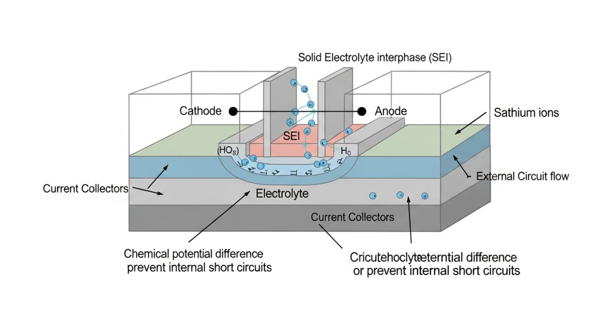
Lithium-Ion Battery Mechanics: These systems operate through the movement of lithium ions between a positive cathode and a negative anode, mediated by an organic electrolyte, following the principles of reversible electrochemical potential defined in ASME-aligned energy storage protocols.
The fundamental operation of a lithium-ion cell relies on the intercalation process. During discharge, lithium ions move from the anode (typically graphite) through the separator to the cathode (typically a metal oxide). This movement releases electrons into the external circuit, providing the electrical power required for grid stabilization or peak shaving.
Cell Chemistry and Energy Density
In my field work, I categorize cells by their specific energy and thermal stability. NMC (Nickel Manganese Cobalt) cells offer high energy density, making them ideal for space-constrained applications. However, they require sophisticated Battery Management Systems (BMS) to monitor voltage and temperature, as they are more prone to thermal runaway than LFP (Lithium Iron Phosphate) variants.
LFP chemistry, while having a lower energy density, provides superior cycle life and thermal stability. For grid-scale BESS, LFP is increasingly the preferred choice due to its robustness under high-cycle duty cycles. The calculation for energy capacity is defined by the product of the nominal voltage and the total ampere-hour capacity of the rack configuration.
Engineering Warning: Thermal Management
Thermal runaway is the most significant risk in BESS design. If the internal temperature exceeds the electrolyte decomposition threshold, an exothermic reaction occurs. Engineers must ensure that the cooling system—whether liquid-cooled or forced-air—is sized to maintain cell temperatures within the manufacturer’s specified operating window, typically between 15 and 35 degrees Celsius, to prevent premature degradation and safety hazards.
Structural and Safety Standards
Designers must adhere to UL 9540 for the safety of energy storage systems. This standard dictates the requirements for the integration of battery modules, inverters, and the enclosure itself. From a piping perspective, the integration of fire suppression systems—often using clean agents or water-mist systems—must be coordinated with the battery rack layout to ensure adequate coverage and rapid response in the event of a cell failure.
Furthermore, the structural integrity of the battery racks must be verified against seismic loads, especially in regions prone to tectonic activity. The mounting hardware and the enclosure base must be designed to withstand the dynamic forces exerted by the heavy battery modules during a seismic event, ensuring that the electrical connections remain intact and the system remains grounded.
Lithium-Ion Performance Tradeoffs: Evaluating the operational benefits against the inherent safety and environmental constraints is critical for selecting the appropriate BESS technology for specific grid applications.
Advantages
- High energy density allows for smaller footprints in urban substations.
- Rapid response times (milliseconds) for frequency regulation services.
- High round-trip efficiency, often exceeding 90 percent.
- Low self-discharge rates compared to other rechargeable chemistries.
- Modular design facilitates scalable capacity expansion.
Disadvantages
- Susceptibility to thermal runaway if cooling systems fail.
- Significant degradation over time due to cycle-life limitations.
- High initial capital expenditure for large-scale installations.
- Complex recycling requirements for end-of-life battery modules.
- Sensitivity to extreme ambient temperatures affecting performance.
BESS Deployment Scenarios: Lithium-ion systems are currently being integrated into diverse industrial and utility-scale environments to solve critical power stability and energy management challenges.
Grid Frequency Regulation
Lithium-ion BESS provides instantaneous power injection or absorption to balance grid frequency fluctuations caused by intermittent renewable sources like wind and solar. This application requires high-power, short-duration discharge capabilities, making NMC chemistry particularly effective for these rapid-response cycles.
Peak Shaving for Industrial Facilities
Large industrial plants utilize BESS to discharge stored energy during peak demand periods, effectively reducing peak load charges from utility providers. This strategy optimizes operational costs and reduces the strain on local distribution transformers during high-consumption manufacturing cycles.
Renewable Energy Time-Shifting
By storing excess energy generated during peak solar production hours, BESS allows for the dispatch of power during evening peak demand. This time-shifting capability is essential for increasing the penetration of solar energy into the grid without requiring massive infrastructure upgrades to transmission lines.
Microgrid Resilience and Backup
In remote or critical infrastructure locations, BESS acts as a primary energy buffer, providing seamless transition to islanded mode during grid outages. This ensures continuous operation of essential services, with the battery system providing the necessary inertia to stabilize the local microgrid voltage.
When designing grid-scale Battery Energy Storage Systems (BESS), engineers must evaluate specific electrochemical performance metrics to ensure long-term reliability and grid compliance. The following table outlines the critical operating parameters that dictate the selection of cell chemistry for stationary storage applications, focusing on energy density, cycle life, and thermal stability thresholds.
These values represent industry-standard benchmarks for utility-scale deployments. It is imperative to note that these metrics are highly sensitive to the Depth of Discharge (DoD) and the ambient operating temperature, which directly influence the degradation rate of the solid electrolyte interphase (SEI) layer within the cells. Always refer to the IEEE 2030.2.1 standard for guidance on testing and performance evaluation of these systems in stationary environments.
| Chemistry Type | Energy Density (Wh/kg) | Cycle Life (80% DoD) | Thermal Stability |
|---|---|---|---|
| LFP (LiFePO4) | 90 – 160 | 3,000 – 6,000 | Excellent |
| NMC (LiNiMnCoO2) | 150 – 250 | 1,000 – 3,000 | Moderate |
| LTO (Li4Ti5O12) | 50 – 80 | 10,000+ | Superior |
Selecting the appropriate chemistry requires balancing the initial capital expenditure against the total cost of ownership over the project lifecycle. For high-frequency regulation services, LTO or LFP chemistries are often preferred due to their superior cycle life and safety profiles, despite lower energy density compared to NMC variants.
The integration of Lithium-Ion Batteries into complex grid architectures requires a deep understanding of the interplay between electrochemical components and power conversion systems. This matrix maps the primary technical entities involved in BESS design, providing a clear reference for engineers tasked with system integration and safety compliance.
Each entity listed below plays a specific role in maintaining the operational integrity of the battery bank. By aligning these components with established international standards such as UL 9540 for safety and IEC 62619 for secondary lithium cells, designers can mitigate risks associated with thermal runaway and premature capacity fade. This mapping is essential for developing robust Battery Management Systems (BMS) that monitor cell voltage, current, and temperature in real-time.
| Entity | Acronym | Primary Function | Standard Reference |
|---|---|---|---|
| Battery Management System | BMS | Cell balancing and safety | IEC 62619 |
| Power Conversion System | PCS | DC to AC inversion | IEEE 1547 |
| State of Charge | SoC | Energy level monitoring | ISO 12405 |
Effective system design relies on the seamless communication between the BMS and the PCS. Ensuring that these entities operate within their defined parameters is the primary defense against catastrophic failure in large-scale energy storage installations.
Before commissioning any BESS installation, a rigorous site verification process is mandatory to ensure compliance with local fire codes and electrical standards. As an engineer, I have observed that most failures occur due to inadequate thermal management or improper grounding during the initial installation phase. This checklist serves as a baseline for field engineers to validate the integrity of the system before energization.
-
Thermal Management Validation: Verify that HVAC systems are sized to maintain cell temperatures within the manufacturer’s specified range (typically 15 to 35 degrees Celsius). -
Grounding and Bonding: Confirm that all metallic enclosures are bonded to the site grounding grid per NFPA 70 (NEC) requirements to prevent potential rise during faults. -
BMS Communication Integrity: Perform a loop check between the battery rack controllers and the master controller to ensure real-time data transmission of voltage and temperature. -
Fire Suppression System: Validate that the clean agent or water-mist suppression system is fully charged and integrated with the facility’s fire alarm control panel. -
Emergency Stop Functionality: Test the physical E-stop buttons to ensure they trigger an immediate disconnection of the DC contactors from the inverter bus.
Site verification is not merely a procedural step; it is the final gatekeeper for operational safety. Always document the results of these checks in a formal commissioning report, ensuring that all deviations from the design specifications are addressed and signed off by the lead engineer before the system is connected to the grid.
The Problem: Unexpected Capacity Fade in High-Ambient Conditions
A 5MW BESS installation in a desert environment experienced a 15% capacity loss within the first six months of operation due to chronic overheating of the battery modules.
- Inadequate airflow design within the containerized battery racks.
- HVAC setpoints were incorrectly configured for the local ambient temperature extremes.
- Lack of redundant temperature sensors leading to localized hot spots.
- BMS software failed to throttle power output during high-temperature excursions.
The Outcome: System Optimization and Recovery
Following a comprehensive root cause analysis, the engineering team implemented a series of corrective measures that restored system stability and prevented further degradation.
- Installed high-capacity industrial HVAC units with dual-redundancy.
- Reconfigured the internal rack layout to optimize laminar airflow across the cells.
- Updated the BMS firmware to include predictive thermal throttling based on ambient trends.
- Achieved a 98% round-trip efficiency recovery within three months of the retrofit.
This case highlights the necessity of designing for the worst-case environmental scenario. In my experience, relying on standard factory settings for HVAC in extreme climates is a recipe for premature asset failure. Always conduct a site-specific thermal load analysis during the FEED phase.
How does cell chemistry influence BESS safety?
The choice of cathode material is the primary determinant of a battery’s thermal stability and safety profile. Lithium Iron Phosphate (LFP) is widely considered the safest chemistry for stationary BESS applications due to its strong covalent phosphorus-oxygen bonds, which prevent oxygen release during thermal runaway.
- NMC chemistries offer higher energy density but are more prone to exothermic reactions at lower temperatures compared to LFP.
- LTO chemistries provide the highest level of safety due to the absence of the solid electrolyte interphase (SEI) layer growth, which is a common failure point.
- Engineers must evaluate the specific energy density versus safety trade-off based on the installation site’s proximity to critical infrastructure.
What is the role of the BMS in grid stability?
The Battery Management System (BMS) acts as the brain of the BESS, ensuring that individual cells operate within their safe electrochemical limits. Without precise BMS control, voltage imbalances between cells can lead to overcharging, which accelerates degradation and increases the risk of fire.
- Active cell balancing redistributes energy from high-voltage cells to low-voltage cells, maximizing the usable capacity of the entire rack.
- Real-time monitoring of State of Charge (SoC) and State of Health (SoH) allows the grid operator to make informed decisions about dispatching power.
- The BMS must communicate seamlessly with the Power Conversion System (PCS) to prevent overcurrent events during rapid grid frequency response.
How do I calculate the cycle life of a BESS?
Calculating cycle life requires understanding the relationship between Depth of Discharge (DoD) and the chemical degradation of the battery. Manufacturers typically provide cycle life data at 80% DoD, but real-world usage often involves varying discharge depths.
- Use the Rainflow-counting algorithm to analyze the cumulative stress on the battery cells based on historical dispatch data.
- Account for the Arrhenius equation when calculating the impact of operating temperature on the chemical reaction rates within the cell.
- Always include a degradation buffer in your design to ensure the system meets its capacity requirements at the end of its intended service life.
What are the primary standards for BESS design?
Adherence to international standards is non-negotiable for grid-scale energy storage. These standards provide the framework for safety, performance, and interoperability across different manufacturers and grid regions.
- UL 9540: Standard for Safety of Energy Storage Systems and Equipment.
- IEC 62619: Safety requirements for secondary lithium cells and batteries for use in industrial applications.
- IEEE 1547: Standard for Interconnecting Distributed Resources with Electric Power Systems.
- NFPA 855: Standard for the Installation of Stationary Energy Storage Systems.
Why is thermal runaway a critical design concern?
Thermal runaway is a self-sustaining exothermic reaction that occurs when the internal temperature of a cell exceeds a critical threshold, leading to the breakdown of the electrolyte and the release of flammable gases.
- The reaction can propagate from a single cell to an entire module and rack if adequate physical separation and fire suppression are not present.
- Designers must implement multi-layered safety systems, including gas detection, smoke detection, and active cooling to mitigate this risk.
- Proper ventilation is essential to prevent the accumulation of explosive gases within the battery enclosure.
How does BESS contribute to grid decarbonization?
BESS enables the integration of intermittent renewable energy sources like wind and solar by providing the necessary flexibility to balance supply and demand in real-time.
- Energy shifting allows excess solar generation during the day to be stored and dispatched during peak evening hours, reducing reliance on fossil-fuel peaker plants.
- Frequency regulation services provided by BESS help maintain grid stability as the share of non-synchronous renewable generation increases.
- By reducing the need for spinning reserves, BESS significantly lowers the carbon intensity of the overall power grid.
Complete Course on
Piping Engineering
Check Now
Key Features
- 125+ Hours Content
- 500+ Recorded Lectures
- 20+ Years Exp.
- Lifetime Access
Coverage
- Codes & Standards
- Layouts & Design
- Material Eng.
- Stress Analysis

📚 Recommended Resources: Lithium-Ion Batteries
Read these Guides
- 📄 Battery Energy Storage Systems: A Comprehensive Engineering Design Guide
- 📄 Green Hydrogen and Green Ammonia Energy Carriers: The Engineering Guide (2026)
- 📄 Battery Energy Storage Systems for Wind Projects: Design and Integration
- 📄 Battery Energy Storage Systems for Solar Projects: A Technical Guide