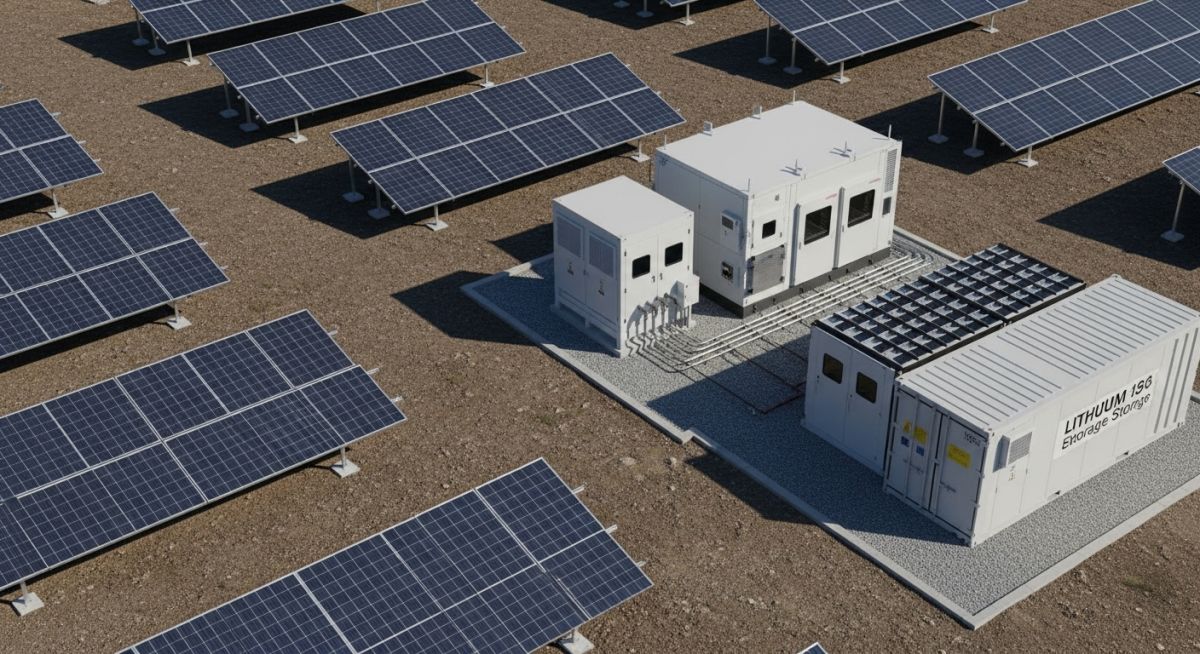
Battery Energy Storage Systems for Solar Projects: A Technical Guide
In my two decades of experience navigating the complexities of industrial power infrastructure, I have observed that the transition to renewable energy is no longer just about generation capacity; it is about the reliability of the delivery. Solar energy, while abundant, is inherently variable. As a piping and systems engineer, I view the integration of Battery Energy Storage Systems (BESS) as the critical “buffer” that transforms solar from a volatile resource into a dispatchable utility-grade power supply.
Designing these systems requires more than just selecting battery modules. It demands a deep understanding of thermal runaway mitigation, power conversion efficiency, and the mechanical balance of plant (BOP) requirements that keep these high-energy density systems operational under extreme environmental conditions. This guide explores the technical architecture required to bridge the gap between solar photovoltaic arrays and the modern electrical grid.
Key Takeaways for Engineering Professionals:
- Understanding the electrochemical limitations of Lithium-Ion versus Flow Battery chemistries.
- Mastering the thermal management requirements for large-scale containerized BESS units.
- Navigating NFPA 855 standards for fire protection and safety in energy storage.
- Optimizing the DC-coupled versus AC-coupled system architecture for maximum round-trip efficiency.
Technical Architecture of Battery Energy Storage Systems
Battery Energy Storage Systems (BESS) design: The systematic engineering of energy density, thermal regulation, and power electronics to ensure safe, efficient, and code-compliant energy dispatch within utility-scale solar environments.
At the heart of any BESS project lies the Battery Management System (BMS), which acts as the brain of the operation. From a mechanical perspective, we must treat the battery container as a high-pressure, high-temperature environment. The primary design challenge is maintaining the cell temperature within the optimal range of 15 to 35 degrees Celsius to prevent accelerated degradation and thermal runaway. In my experience, the cooling system—whether liquid-cooled or forced-air—is the most common point of failure in poorly designed installations.
When calculating the capacity of a BESS, we must account for the Depth of Discharge (DoD) and the State of Health (SoH) over the project’s 20-year lifecycle. The energy capacity (E) is defined by the product of the nominal voltage (V) and the total ampere-hour capacity (Ah) of the cell strings. However, the usable energy is significantly lower due to the round-trip efficiency (RTE) losses, which typically range between 85% and 92% for modern Lithium Iron Phosphate (LFP) systems.
Critical Design Limitation: Thermal Runaway
Per NFPA 855, the design must incorporate gas detection and fire suppression systems capable of managing off-gassing events. Mechanical engineers must ensure that the enclosure ventilation system is sized to prevent the accumulation of flammable gases, such as hydrogen or carbon monoxide, during a cell failure event. Failure to account for these volumetric flow rates can lead to catastrophic enclosure rupture.
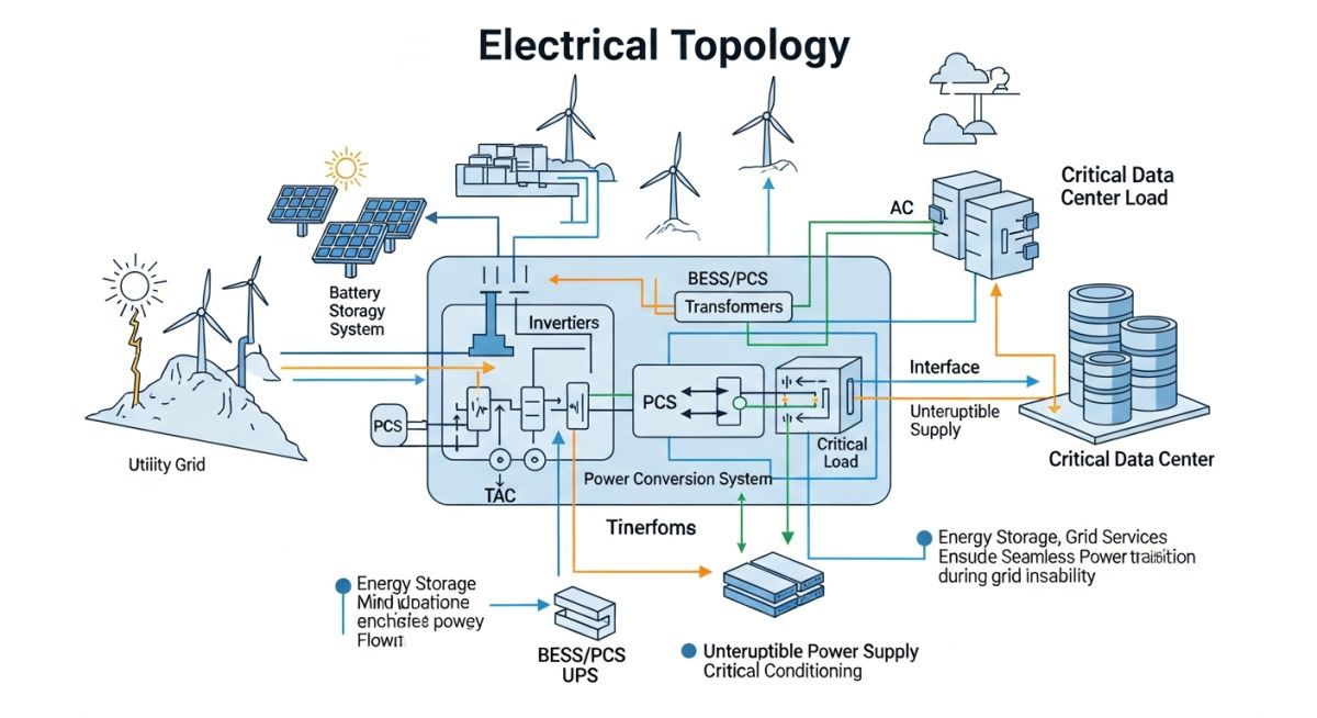
The integration of the BESS with the solar array can be achieved through two primary topologies: DC-coupled and AC-coupled. In a DC-coupled system, the solar PV and the battery share a common inverter, which reduces conversion losses by eliminating the need for a separate DC-to-AC conversion step for the battery. Conversely, AC-coupled systems offer greater flexibility for retrofitting existing solar farms, as the BESS operates as an independent grid-tied asset. The choice between these topologies depends on the specific project requirements for ramp-rate control and frequency regulation.
Finally, we must consider the structural integrity of the mounting racks and the seismic requirements for the battery containers. Following ASCE 7 standards, the foundation design must account for the high concentrated loads of the battery modules. In my field work, I have seen projects delayed by months due to inadequate soil bearing capacity analysis for the heavy battery containers, emphasizing the need for early-stage geotechnical coordination.
BESS performance trade-offs: A critical evaluation of electrochemical storage benefits versus the inherent operational risks and maintenance requirements in utility-scale power systems.
Advantages
- Peak Shaving: Effectively reduces demand charges by discharging during high-tariff periods.
- Frequency Regulation: Provides sub-second response times to stabilize grid frequency fluctuations.
- Solar Firming: Converts intermittent solar generation into a predictable, dispatchable energy profile.
- Black Start Capability: Enables grid restoration without external power in the event of a total blackout.
Disadvantages
- High Capital Expenditure: Significant upfront costs for battery modules and power conversion equipment.
- Degradation Sensitivity: Capacity loss over time requires complex augmentation strategies to maintain performance.
- Thermal Management Complexity: Requires robust HVAC and liquid cooling systems to prevent fire risks.
- Regulatory Hurdles: Stringent permitting and safety compliance (NFPA 855) can extend project timelines.
Industrial energy storage deployment: Strategic implementation of BESS across diverse sectors to optimize power quality, ensure operational continuity, and maximize renewable energy utilization.
Utility-Scale Grid Stabilization
Large-scale BESS installations act as virtual power plants, providing essential ancillary services to transmission system operators. By injecting or absorbing power in milliseconds, these systems prevent grid instability caused by the rapid ramp-up or ramp-down of solar generation during cloud cover events.
Remote Microgrid Electrification
In off-grid industrial sites, such as mining operations or remote processing plants, BESS allows for the integration of high-penetration solar PV. This reduces reliance on expensive, high-emission diesel generators by storing excess daytime solar energy for use during nighttime operations.
Commercial and Industrial (C&I) Peak Shaving
Manufacturing facilities utilize BESS to mitigate high demand charges by discharging stored energy during peak operational hours. This strategy significantly lowers the monthly utility bill while providing a secondary benefit of uninterruptible power supply (UPS) functionality for sensitive equipment.
EV Charging Infrastructure Support
High-speed electric vehicle charging stations often face grid capacity constraints that prevent simultaneous high-power charging. BESS acts as a buffer, drawing power from the grid at a constant, lower rate and discharging it at high power to vehicles, thereby avoiding expensive grid infrastructure upgrades.
When evaluating Battery Energy Storage Systems for solar integration, engineers must prioritize specific performance metrics that dictate the long-term viability of the asset. These parameters are not merely theoretical; they define the operational envelope for power conversion systems and thermal management units under varying ambient conditions. In my experience, failing to account for the degradation curves of lithium-ion chemistries at high ambient temperatures leads to premature capacity loss and significant financial penalties under power purchase agreements.
The following table outlines the critical performance benchmarks required for grid-scale applications. These values align with IEEE 2030.2 standards for energy storage systems. Note that round-trip efficiency is highly dependent on the depth of discharge and the frequency of cycling, which must be modeled during the initial front-end engineering design phase to ensure the system meets the required energy throughput over its twenty-year design life.
The successful deployment of a Battery Energy Storage System requires a deep understanding of the interconnected components that form the balance of plant. From the battery management system (BMS) that monitors individual cell voltages to the power conversion system (PCS) that facilitates bidirectional energy flow, each entity must be mapped to its respective control logic and safety standard. This matrix serves as a foundational reference for project managers and electrical engineers tasked with system integration.
By standardizing the nomenclature and technical requirements across the project lifecycle, we reduce the risk of interface mismatches between the battery modules and the grid-side infrastructure. It is essential to recognize that the BMS is the primary defense against thermal runaway, and its communication protocols must be robust enough to handle high-speed data transmission during transient grid events. The following matrix categorizes these entities based on their primary function within the BESS architecture.
| Entity | Function | Standard |
|---|---|---|
| BMS | Cell Monitoring & Balancing | UL 1973 |
| PCS | DC to AC Conversion | IEEE 1547 |
| EMS | Grid Dispatch Optimization | IEC 61850 |
Site verification is the final gate before commissioning a Battery Energy Storage System. In my years of field experience, I have observed that most commissioning delays stem from inadequate site preparation or failure to verify the communication handshake between the Energy Management System (EMS) and the local utility grid controller. This checklist provides a structured approach to ensuring that all physical and logical requirements are met before energization.
- Foundation Integrity: Verify that the concrete pad meets the structural load requirements for the containerized battery units, including seismic bracing as per local building codes.
- Thermal Management: Confirm that HVAC systems are operational and that the fire suppression system is fully charged and integrated with the site alarm panel per NFPA 855.
- Grounding & Bonding: Ensure the main grounding grid is tested for impedance levels, and all metallic enclosures are bonded to the common ground to prevent potential rise during fault conditions.
- Communication Links: Validate the fiber optic or Ethernet connectivity between the PCS, BMS, and the site SCADA system to ensure real-time data telemetry.
- Safety Signage: Confirm that all arc flash labels, high-voltage warnings, and emergency shutdown procedures are clearly posted in accordance with OSHA requirements.
Once these items are verified, the site is ready for the final insulation resistance testing and the initial charge cycle. Always maintain a detailed log of these verification steps, as they form the basis of the project’s handover documentation and are essential for future maintenance audits.
Problem: Thermal Instability in High-Ambient Desert Environment
A 50MW solar-plus-storage project in a high-temperature desert region experienced frequent derating of the BESS units during peak summer months, leading to significant revenue loss.
- Inadequate airflow design within the containerized battery enclosures.
- Ambient temperatures exceeding the design rating of the HVAC units.
- High internal heat generation during rapid discharge cycles.
- Lack of redundant cooling capacity for critical battery racks.
Outcome: Optimized Thermal Management and Sustained Output
By retrofitting the cooling systems and implementing a predictive thermal management algorithm, the project achieved full capacity utilization even during extreme heat events.
- Increased system availability by 15% during peak demand hours.
- Reduced battery degradation rate by 8% through improved temperature uniformity.
- Successful integration of liquid cooling loops for high-density modules.
- Enhanced safety profile through real-time thermal monitoring and automated derating.
The recommendation for future projects is to conduct a detailed computational fluid dynamics (CFD) analysis during the design phase to ensure that the cooling strategy is robust enough to handle the worst-case ambient temperature scenarios for the specific project location.
Frequently Asked Engineering Questions
How does BESS improve solar project bankability?
- Participation in lucrative ancillary service markets like frequency regulation.
- Avoidance of curtailment during periods of oversupply.
- Stabilization of revenue streams through energy arbitrage.
- Compliance with grid code requirements for renewable energy plants.
What are the primary safety standards for BESS?
How is BESS round-trip efficiency calculated?
- Includes losses from the power conversion system (PCS).
- Includes internal battery resistance and chemical losses.
- Includes auxiliary power consumption for HVAC and BMS.
- Measured at the point of common coupling (PCC) for system-level accuracy.
What is the role of the BMS in BESS?
- Cell balancing to prevent overcharge or deep discharge of individual cells.
- State of Charge (SOC) and State of Health (SOH) estimation.
- Thermal monitoring and protection against over-temperature conditions.
- Communication with the PCS to manage charge and discharge limits.
How does BESS support grid frequency regulation?
- Responds to frequency deviations by adjusting power output.
- Provides synthetic inertia to stabilize grid frequency.
- Operates in both up-regulation and down-regulation modes.
- Reduces the need for spinning reserves on the grid.
What are the main degradation factors for BESS?
- High operating temperatures accelerating chemical side reactions.
- High depth of discharge (DOD) cycles reducing cycle life.
- High C-rates causing mechanical stress on electrode materials.
- Calendar aging due to storage at high state of charge.
Complete Course on
Piping Engineering
Check Now
Key Features
- 125+ Hours Content
- 500+ Recorded Lectures
- 20+ Years Exp.
- Lifetime Access
Coverage
- Codes & Standards
- Layouts & Design
- Material Eng.
- Stress Analysis
