Liquified Natural Gas Engineering Design and Cryogenic Piping Systems
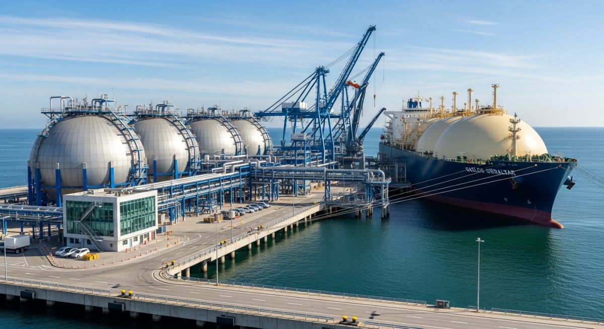
In my 20-plus years of designing cryogenic piping systems, I have watched the global energy landscape shift dramatically toward cleaner fossil fuels. Liquified Natural Gas (LNG) stands at the absolute center of this transition. When we design systems to handle a fluid at minus 162 degrees Celsius, the margin for error is zero. Standard carbon steel becomes as brittle as glass at these temperatures, meaning we must throw out conventional piping rules and design with absolute cryogenic precision.
Managing an LNG facility requires a deep understanding of thermodynamics, material science, and specialized piping codes. From the pretreatment units where we strip out carbon dioxide and water to prevent freezing, to the massive liquefaction cold boxes, every single component must be engineered to handle extreme thermal contraction. I have spent years troubleshooting thermal stress failures, and I can tell you that success lies in the details of your stress analysis and material selection.
Key Engineering Takeaways
- Understand the critical role of ASME B31.3 Chapter IX in governing high-pressure, low-temperature cryogenic piping design.
- Learn how to calculate and mitigate massive thermal contraction in stainless steel and nickel-alloy piping systems.
- Master the process steps of LNG production, including acid gas removal, dehydration, and liquefaction cycles.
- Identify the physical properties that make LNG safe to transport but highly hazardous if trapped in unvented piping runs.
How Liquified Natural Gas Behaves Under Cryogenic Conditions
When natural gas is purified and cooled to its boiling point of minus 162 degrees Celsius, its volume shrinks by a factor of approximately 600. This volumetric reduction is what makes global shipping feasible. However, handling a liquid at this temperature introduces severe mechanical challenges. The piping designer must select materials that retain their impact strength and ductility at ultra-low temperatures.
In my practice, the primary material of choice is ASTM A312 Grade TP316L or TP304L stainless steel. These austenitic stainless steels do not undergo a transition from ductile to brittle fracture at cryogenic temperatures, unlike carbon steels. For larger storage tanks and specialized applications, 9% nickel alloy steel is also widely utilized due to its low coefficient of thermal expansion and high tensile strength.
Calculating Thermal Contraction in Cryogenic Piping
One of the most critical steps in cryogenic engineering is calculating the physical contraction of the piping system as it cools down from ambient installation temperature to operating temperature. Let us walk through a real-world calculation for a straight run of stainless steel piping.
Thermal Contraction Formula:
dL = L * alpha * dT
Where:
- dL = Total change in pipe length (meters)
- L = Initial length of the piping run (meters)
- alpha = Mean coefficient of thermal expansion (m/m/°C)
- dT = Temperature difference between installation and operation (°C)
Let us assume we have a 100-meter straight run of ASTM A312 TP316L piping. The installation temperature is 21 degrees Celsius, and the operating temperature with LNG is minus 162 degrees Celsius.
- Calculate the temperature differential: dT = -162 – 21 = -183°C
- Identify the mean coefficient of thermal expansion for TP316L stainless steel over this temperature range: alpha = 14.5 * 10^-6 m/m/°C
- Calculate the contraction: dL = 100 * (14.5 * 10^-6) * (-183) = -0.265 meters
This calculation reveals that our 100-meter pipe will shrink by 265 millimeters (over 10 inches) when LNG is introduced. If this contraction is not absorbed by expansion loops, offsets, or bellows, the resulting thermal stresses will easily exceed the allowable limits defined in ASME B31.3 Chapter IX, leading to structural failure of the piping anchors or flange leakage.
I cannot stress this enough: never design a piping segment where cryogenic liquid can be trapped between two closed valves. If LNG is isolated in a pipe section without a relief path, ambient heat will cause the liquid to vaporize. Because the liquid-to-gas expansion ratio is 1:600, the pressure inside the pipe will rise exponentially, resulting in a catastrophic explosive rupture. Always install hydrostatic relief valves (HRVs) in every potential pocket.
The LNG Production Process Chain
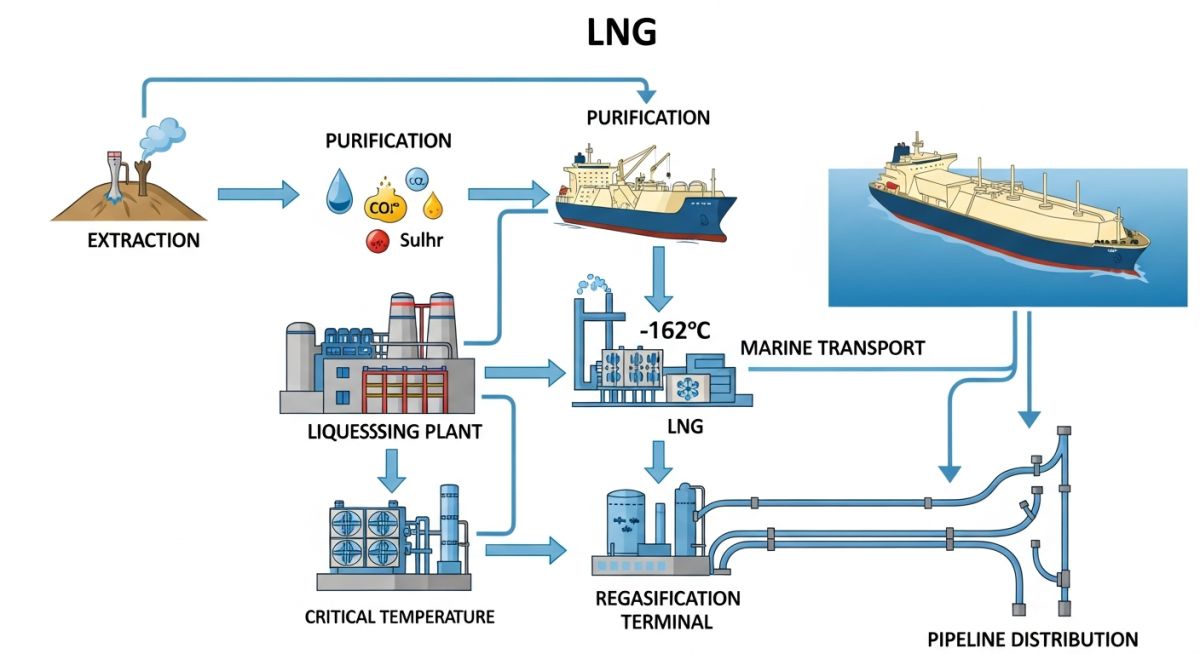
Before natural gas can be liquified, it must undergo extensive pretreatment. Raw natural gas from the wellhead contains impurities that would freeze solid at cryogenic temperatures, plugging the heat exchangers. The process begins with acid gas removal to strip out carbon dioxide and hydrogen sulfide using amine solvents. Next, the gas passes through molecular sieve dehydration units to reduce water content to less than 0.1 parts per million.
Once dehydrated, the gas enters a mercury removal unit, as mercury can cause catastrophic liquid metal embrittlement in aluminum heat exchangers. Heavy hydrocarbons are then separated out to prevent freezing. Finally, the purified methane-rich stream is routed to the main cryogenic heat exchanger (MCHE), where it is liquified using advanced refrigeration cycles such as the Propane Pre-cooled Mixed Refrigerant (C3MR) process or the Cascade process.
Physical Properties of Liquified Natural Gas
Designing safe containment and transport systems requires precise knowledge of LNG’s physical constants. Below is the engineering data sheet that I reference during the initial design phase of any LNG loading terminal or regasification facility.
| Physical Property | Typical Value | Unit | Engineering Significance |
|---|---|---|---|
| Boiling Point | -162 to -160 | °C | Determines the minimum design temperature for piping and vessels. |
| Liquid Density | 420 to 460 | kg/m³ | Used for static head calculations and structural support design. |
| Gas-to-Liquid Ratio | 600:1 | Vol/Vol | Governs relief valve sizing and vapor dispersion modeling. |
| Flammability Limits | 5 to 15 | % in Air | Defines hazardous area classification zones around equipment. |
| Autoignition Temp | 580 | °C | Critical for fire protection and risk assessment studies. |
This matrix maps the core technical entities, structural acronyms, and physical parameters to their respective industry standards.
| Entity / Acronym | Full Description | Primary Standard Reference | Key Design Parameter |
|---|---|---|---|
| MCHE | Main Cryogenic Heat Exchanger | ASME Section VIII Div 1 | Thermal stress limits, heat transfer coefficient |
| BOG | Boil-Off Gas | NFPA 59A | Vapor recovery compressor capacity, tank pressure control |
| ESD | Emergency Shutdown System | ISA S84.01 / IEC 61511 | Valve closure time, safety integrity level (SIL) |
| SPI | Single Point Ignition | API RP 521 | Flare stack height, radiation limits at grade |
Pre-Commissioning Checklist for Cryogenic Piping Systems
Before introducing LNG into any piping system, a rigorous pre-commissioning protocol must be executed. Any residual moisture inside the pipe will freeze instantly, forming ice plugs that can block flow or damage control valves. The checklist below represents the exact field verification steps I enforce on-site.
Field Verification Steps
Perform leak testing using dry nitrogen or helium. Never use water for hydrotesting cryogenic lines unless absolute drying procedures are guaranteed afterward.
Purge the piping system with dry nitrogen until the outlet dew point is verified to be below minus 40 degrees Celsius. This ensures all moisture is eliminated.
Verify that all pipe shoes are insulated (cryogenic cold shoes made of high-density polyurethane or micarta) to prevent thermal bridging to the steel structure.
Check that all spring hangers are set to their cold design positions and that travel stops are removed prior to the cooldown phase.
Purge the system until the oxygen concentration is below 1% to eliminate any risk of forming a flammable mixture when hydrocarbons are introduced.
Field Case Study: Real-World Application
The Problem: Thermal Shock and Piping Deformation
During the commissioning of a major LNG export terminal in the Middle East, operators bypassed the established slow-cooldown protocol. They introduced liquid LNG directly into a warm, 24-inch stainless steel loading line. The sudden thermal shock caused the bottom of the pipe to contract rapidly while the top remained warm. This extreme temperature gradient caused the pipe to bow upward, lifting off its supports and overloading the adjacent pump nozzle, resulting in flange deformation and a minor hydrocarbon release.
The Outcome: Controlled Cooldown and Sensor Integration
I was brought in to lead the root cause analysis. We redesigned the cooldown system by integrating a dedicated liquid nitrogen spray nozzle at the header inlet. This allowed for a controlled, gradual temperature drop of no more than 1.5 degrees Celsius per minute. We also installed skin temperature sensors along the top and bottom of the pipe to monitor thermal gradients in real-time. The piping was realigned, and subsequent cooldowns were executed flawlessly without any structural deformation.
My direct recommendation for any cryogenic project is to automate the cooldown sequence. Relying on manual valve adjustments during cooldown introduces human error that can lead to multi-million dollar piping failures.
Frequently Asked Engineering Questions
Why is carbon steel not used in LNG piping systems?
What is the purpose of a cryogenic cold shoe?
How is boil-off gas (BOG) managed in LNG facilities?
What are the primary design codes for LNG facilities?
Why is mercury removal critical in LNG pretreatment?
How do you absorb thermal contraction in long LNG pipelines?
===
Complete Course on
Piping Engineering
Check Now
Key Features
- 125+ Hours Content
- 500+ Recorded Lectures
- 20+ Years Exp.
- Lifetime Access
Coverage
- Codes & Standards
- Layouts & Design
- Material Eng.
- Stress Analysis

📚 Recommended Resources: Natural Gas
Read these Guides
- 📄 Hydrogen Pipeline vs Natural Gas Pipeline vs HVAC Powerline vs HVDC Powerline: Which is the Lowest-Cost Energy Transport Form?
- 📄 Managing Flow Assurance with Gas Hydrate Chemical Injection
- 📄 How Civil Engineers in Oil and Gas Design Resilient Infrastructure
- 📄 Selecting the Best Piping Supports in Oil and Gas