Managing Flow Assurance with Gas Hydrate Chemical Injection
In my 20 years of managing subsea piping networks, nothing tests an engineer’s resolve quite like the sudden, silent restriction of a pipeline by gas hydrates. These crystalline ice-like structures form rapidly under high-pressure and low-temperature conditions, threatening to plug lines, damage downstream equipment, and halt production entirely.
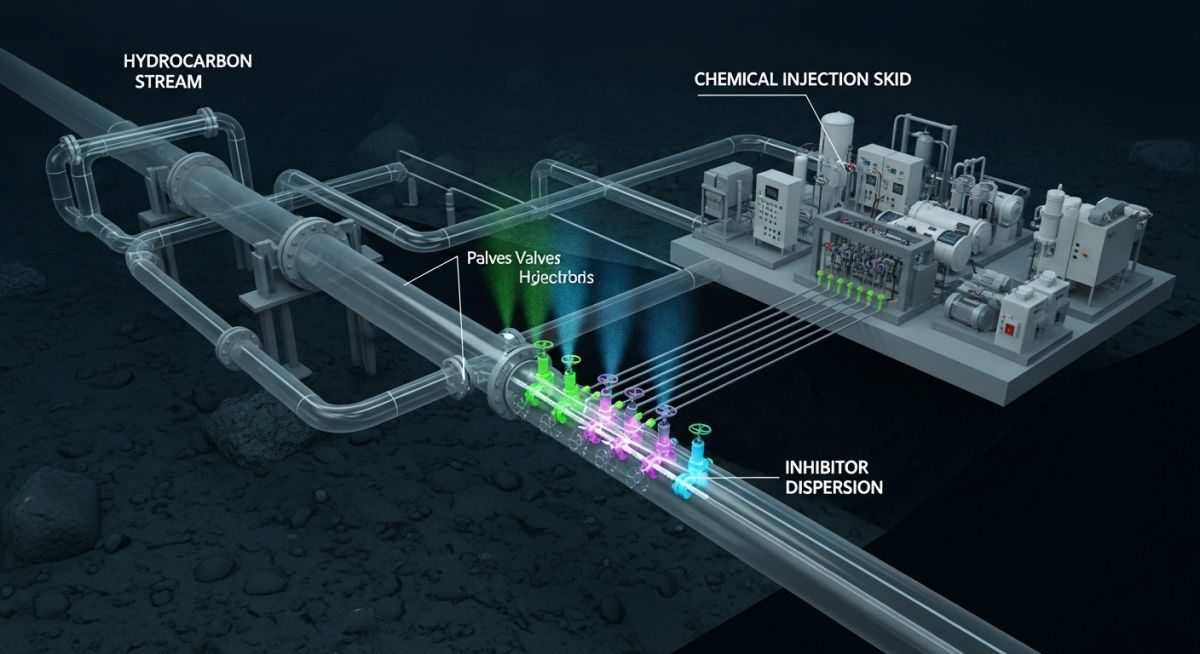
To combat this, we rely on robust chemical injection strategies. By introducing specific chemical inhibitors directly into the fluid stream, we alter the thermodynamic equilibrium or disrupt the physical growth of these crystals. This article details the engineering principles, design calculations, and field practices required to implement an effective injection system.
Key Engineering Takeaways:
- Understand the thermodynamic triggers of hydrate formation in high-pressure systems.
- Differentiate between Thermodynamic Inhibitors (THIs) and Low Dosage Hydrate Inhibitors (LDHIs).
- Master the Hammerschmidt equation for calculating precise inhibitor dosage rates.
- Implement robust field verification protocols to protect subsea assets.
Why Gas Hydrate Chemical Injection is Necessary
Hydrate Inhibition Mechanisms: The chemical alteration of the water phase’s thermodynamic equilibrium or physical crystallization kinetics prevents solid hydrate formation under high-pressure, low-temperature operating envelopes defined by ISO 13628-5.
Gas hydrates are clathrate compounds where water molecules form a solid cage-like structure around guest gas molecules, such as methane, ethane, or carbon dioxide. These structures form at temperatures well above the freezing point of pure water when pressures are elevated. In subsea pipelines, where temperatures often drop to 4 degrees Celsius and pressures exceed 50 bar, hydrate formation is a constant threat.
Thermodynamic Inhibitors (THIs)
Thermodynamic inhibitors, such as Methanol (MeOH) and Monoethylene Glycol (MEG), work by shifting the hydrate equilibrium curve to lower temperatures and higher pressures. They achieve this by forming strong hydrogen bonds with water molecules, reducing the chemical activity of water and making it unavailable for hydrate cage formation.
To calculate the required concentration of a thermodynamic inhibitor, we utilize the classic Hammerschmidt equation:
Where:
• dT = Hydrate temperature depression in degrees Fahrenheit.
• W = Weight percent of the inhibitor in the liquid phase.
• M = Molecular weight of the inhibitor (Methanol = 32.04 g/mol, MEG = 62.07 g/mol).
• K = Empirical constant (2335 for Methanol, 2700 for Monoethylene Glycol).
Low Dosage Hydrate Inhibitors (LDHIs)
Unlike THIs, which require high concentrations (often 20% to 50% of the water phase), LDHIs are effective at concentrations of 0.5% to 3.0% by volume. They are categorized into two primary types:
- Kinetic Hydrate Inhibitors (KHIs): Water-soluble polymers that adsorb onto the surface of growing hydrate crystal nuclei, blocking further growth and delaying nucleation for a period longer than the fluid residence time in the pipeline.
- Anti-Aggregants (AAs): Surface-active agents that allow hydrates to form but prevent them from agglomerating into large, solid plugs. The hydrates remain as a transportable slurry within the liquid hydrocarbon phase.
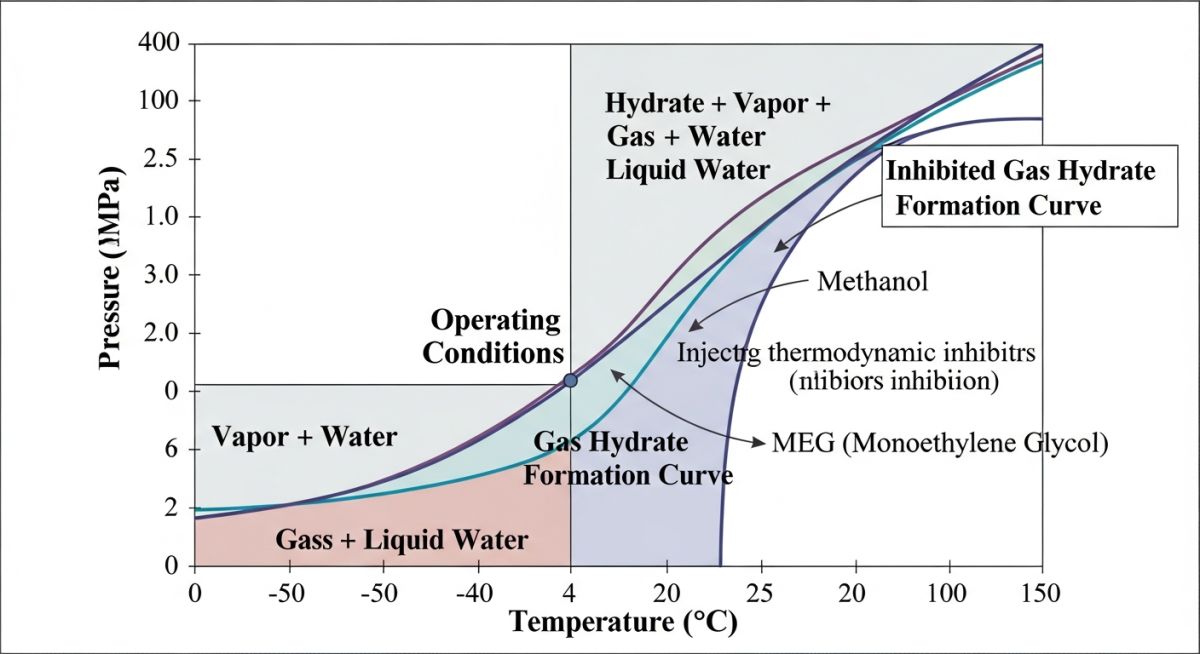
Selecting between THIs and LDHIs depends heavily on the subsea system’s subcooling temperature (the difference between the operating temperature and the hydrate formation temperature). KHIs generally lose effectiveness at subcooling levels exceeding 15 degrees Celsius, whereas THIs can handle extreme subcooling if injected in sufficient quantities.
Selecting the correct chemical inhibitor requires a detailed evaluation of physical properties, operating envelopes, and economic factors. The table below compares the primary inhibitors used in modern offshore flow assurance.
| Inhibitor Type | Typical Dosage (wt%) | Max Subcooling Limit | Recovery Requirement | Primary Operational Risk |
|---|---|---|---|---|
| Methanol (MeOH) | 15 – 40% | > 30 °C | Rarely Recovered (Lost) | High volatility, toxicity, refinery penalties |
| Monoethylene Glycol (MEG) | 30 – 60% | > 30 °C | Highly Recoverable (Regen) | High viscosity at low temp, salt scaling |
| Kinetic Inhibitors (KHI) | 0.5 – 2.0% | < 15 °C | Non-recoverable | Water chemistry sensitivity, polymer fouling |
| Anti-Aggregants (AA) | 0.5 – 3.0% | < 20 °C | Non-recoverable | Requires minimum oil cut, high cost |
To ensure compliance with international design standards, engineers must map physical parameters to specific code requirements. The matrix below outlines these relationships.
| System Component | Applicable Standard | Key Parameter | Design Objective |
|---|---|---|---|
| Injection Piping | ASME B31.3 | Wall Thickness & Pressure Rating | Withstand high-pressure injection pump discharge |
| Subsea Umbilicals | ISO 13628-5 | Fluid Compatibility & Collapse Resistance | Prevent chemical degradation of thermoplastic hoses |
| Safety Systems | API RP 14C | Overpressure Protection & Interlocks | Prevent line rupture during blocked injection paths |
Designing Systems for Gas Hydrate Chemical Injection
Chemical Injection System Design: The engineering and integration of high-pressure positive displacement pumps, chemical storage tanks, and subsea injection valves ensure precise inhibitor delivery under ASME B31.3 and API RP 14G guidelines.
Designing a reliable chemical injection system requires careful attention to detail. Because these systems operate at pressures higher than the pipeline operating pressure, positive displacement pumps (typically plunger or diaphragm types) are required. The piping, valves, and fittings must be rated for the maximum pump discharge pressure, which often includes a significant margin over the pipeline design pressure.
Field Verification & Commissioning Checklist:
-
Verify that all chemical injection lines are hydrostatically tested to 1.5 times the maximum design pressure in accordance with ASME B31.3. -
Perform chemical compatibility testing on all seals, O-rings, and umbilical liners to prevent degradation from aggressive solvents like methanol. -
Calibrate the stroke length and frequency of positive displacement pumps to match the calculated Hammerschmidt dosage rates. -
Confirm that subsea injection valves and check valves are functioning correctly to prevent backflow of hydrocarbons into the umbilical. -
Establish low-flow and high-pressure alarms on the injection skid to alert operators immediately of line blockages or pump failures.
Field Case Study: Real-World Application
In my experience, theoretical designs must always be validated by real-world field data. Below is a case study from a deepwater subsea tieback project in the Gulf of Mexico where a critical flow assurance failure occurred due to inadequate chemical injection.
The Problem: Subsea Tieback Blockage
During a planned shutdown of a 12-inch subsea wet gas tieback pipeline, the operator failed to perform a proper methanol flush before the system cooled down to ambient sea temperature (4 degrees Celsius). The pipeline pressure remained at 90 bar.
Upon attempting to restart the field, operators noticed a complete lack of flow and a rapid pressure build-up upstream of the subsea manifold. A massive gas hydrate plug had formed, completely blocking a 200-meter section of the pipeline.
The Outcome: Controlled Remediation
To safely remediate the plug without causing a catastrophic pipeline rupture (which can occur if a plug is depressurized from one side only, causing it to act as a high-velocity projectile), we implemented a dual-sided depressurization strategy.
Simultaneously, we initiated continuous high-pressure methanol injection directly upstream of the plug via the subsea umbilical. Over a period of 72 hours, the methanol successfully depressed the hydrate equilibrium temperature, slowly melting the plug from the outer edges inward. Flow was safely restored without damaging the subsea piping or valves.
This incident highlights the necessity of strict adherence to shutdown and startup protocols. Chemical injection is not merely an operational option; it is a critical safety barrier that must be maintained diligently.
Optimizing Gas Hydrate Chemical Injection Operations
Hydrate Management Optimization: The continuous monitoring of pipeline operating envelopes and chemical dosage rates minimizes operational expenditure while maintaining flow assurance under ASME B31.8 guidelines.
What is the primary difference between THIs and LDHIs?
How does the Hammerschmidt equation assist in system design?
Why is methanol preferred over MEG in certain subsea applications?
What are the environmental risks associated with chemical injection?
Can KHIs be used in systems with high subcooling?
Which standards govern the design of subsea chemical injection systems?
===
Complete Course on
Piping Engineering
Check Now
Key Features
- 125+ Hours Content
- 500+ Recorded Lectures
- 20+ Years Exp.
- Lifetime Access
Coverage
- Codes & Standards
- Layouts & Design
- Material Eng.
- Stress Analysis
