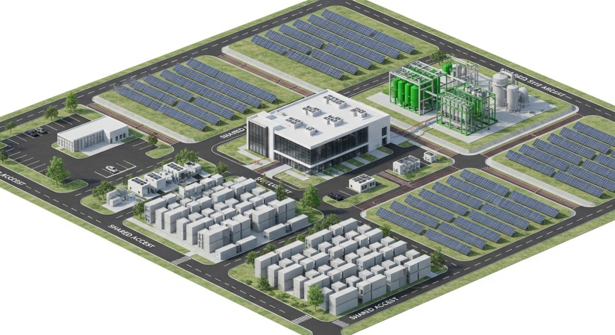
Integrated Site Development Workflow for Modern Infrastructure Projects
In my two decades of experience managing large-scale industrial projects, I have observed that the most common cause of budget overruns is the failure to integrate site development workflows early in the design phase. Whether you are developing a hyperscale data center or a green hydrogen plant, the site is not just a plot of land; it is a complex, interconnected system of soil mechanics, drainage patterns, and utility corridors.
This guide outlines the rigorous, multi-disciplinary approach required to de-risk your project from the initial topographical survey through to final earthwork optimization. By aligning your civil, structural, and process engineering teams under a unified development framework, you can significantly reduce site preparation costs and avoid the catastrophic delays often associated with unforeseen subsurface conditions or flood mitigation failures.
Key Takeaways
- Standardize site selection criteria using multi-criteria decision analysis (MCDA).
- Leverage geotechnical data to minimize cut-and-fill volumes during earthwork.
- Integrate flood study results into the Finished Pad Level (FPL) design.
- Coordinate utility routing early to prevent clashes with structural foundations.
Technical Deep-Dive: Integrated Site Development Workflow
Integrated Site Development Workflow: A comprehensive engineering process that aligns geotechnical, hydrological, and topographical constraints to ensure structural integrity and operational efficiency for complex industrial facilities.
The foundation of any successful project lies in the accuracy of the initial site investigation. When we talk about an integrated workflow, we are looking at the convergence of ASCE standards for site characterization and ASTM protocols for soil testing. The process begins with a high-resolution topographical survey, which serves as the base layer for all subsequent civil and process design.
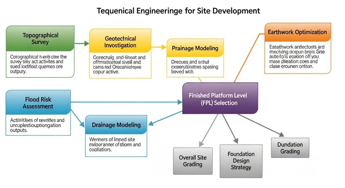
Geotechnical Investigation and Earthwork Optimization
Geotechnical reports must go beyond simple bearing capacity values. For hydrogen and BESS projects, we must evaluate the potential for soil liquefaction and differential settlement, especially when dealing with heavy battery containers or high-pressure storage vessels. I always mandate a minimum of one borehole per 500 square meters for critical infrastructure areas to ensure the soil profile is fully understood.
Field Warning: Subsurface Variability
Never rely on regional geological maps for site-specific design. In my experience, localized pockets of expansive clay or high water tables can increase foundation costs by up to 40% if not identified during the initial geotechnical investigation phase. Always perform a site-specific seismic hazard analysis if the project is located in a high-risk zone.
Finished Pad Level (FPL) and Flood Mitigation
Determining the FPL is a balancing act between flood risk mitigation and earthwork costs. We calculate the FPL by adding the 100-year flood elevation to a safety freeboard, typically 300mm to 600mm depending on local regulations. The goal is to minimize the volume of imported fill while ensuring the site remains operational during extreme weather events.
To optimize earthworks, we utilize mass-haul diagrams to balance cut and fill volumes across the site. By adjusting the FPL by even 100mm, we can often shift thousands of cubic meters of soil, directly impacting the project’s carbon footprint and budget. This iterative process requires constant communication between the civil team and the process engineers to ensure that utility invert levels are not compromised by the final site grading.
Integrated Development Analysis: A critical evaluation of the benefits and risks associated with adopting a unified site development strategy for large-scale industrial infrastructure.
Advantages
- Significant reduction in change orders during the construction phase.
- Optimized earthwork volumes lead to lower site preparation costs.
- Improved coordination between civil, structural, and electrical disciplines.
- Enhanced risk management through early identification of subsurface hazards.
- Faster permitting processes due to comprehensive documentation.
Disadvantages
- Higher upfront engineering costs for detailed site investigations.
- Requires longer initial design timelines to synchronize all data.
- Demands high-level expertise in multi-disciplinary project management.
- Potential for “analysis paralysis” if data integration is not strictly managed.
- Increased reliance on accurate, high-fidelity survey data.
Infrastructure Deployment Scenarios: Practical applications of integrated site development workflows across diverse energy and data sectors.
Hyperscale Data Center Campus
Data centers require extreme precision in site leveling to support heavy server racks and complex cooling infrastructure. An integrated workflow ensures that the high-load bearing requirements of the building foundations are perfectly aligned with the site’s drainage and utility routing, preventing future structural settlement issues.
Utility-Scale Solar PV Arrays
For large solar farms, the primary challenge is managing vast, uneven terrain while minimizing soil disturbance. By using integrated topographical modeling, engineers can design racking systems that adapt to the natural slope, significantly reducing the need for extensive grading and preserving the site’s natural drainage patterns.
Battery Energy Storage Systems (BESS)
BESS projects demand strict fire safety and thermal management, which are heavily influenced by site layout and soil thermal conductivity. Integrating geotechnical data allows for the design of foundation systems that optimize heat dissipation while ensuring the site is protected from potential flood events that could compromise battery safety.
Green Hydrogen Production Facilities
Hydrogen plants involve high-pressure storage and complex piping networks that are sensitive to ground movement. An integrated development approach ensures that all process equipment is situated on stable, well-drained ground, minimizing the risk of pipe stress and ensuring compliance with stringent safety standards for hazardous material handling.
In my two decades of managing large-scale industrial site development, I have observed that the success of complex projects—ranging from hyperscale data centers to green hydrogen facilities—hinges on the rigorous application of standardized site parameters. These benchmarks serve as the foundational constraints for civil, structural, and electrical integration, ensuring that the physical site footprint aligns with the operational requirements of the facility.
The following table outlines the critical design parameters I prioritize during the initial feasibility and detailed design phases. By adhering to these specific metrics, engineering teams can mitigate risks associated with soil bearing capacity, drainage efficiency, and structural settlement, which are often the primary drivers of cost overruns in multi-disciplinary energy projects.
| Parameter | Standard Reference | Typical Target Range |
|---|---|---|
| Soil Bearing Capacity | ASTM D2487 | 150 – 300 kPa |
| Site Grading Slope | ASCE 7-22 | 0.5% – 2.0% |
| Stormwater Retention | EPA SWPPP | 100-year storm event |
| BESS Foundation Load | NFPA 855 | 20 – 50 kN/m2 |
These values are not merely suggestions; they represent the minimum thresholds required to maintain structural integrity under extreme environmental loading. When evaluating a site, I always cross-reference these targets against local geotechnical reports to ensure that the proposed earthwork strategy remains economically viable without compromising safety.
The integration of diverse technologies—such as Battery Energy Storage Systems (BESS) and Hydrogen Electrolyzers—requires a sophisticated mapping of technical entities to ensure cross-disciplinary compatibility. In my experience, the failure to align these specifications early in the design lifecycle leads to significant rework during the construction phase, particularly regarding utility routing and foundation requirements.
This matrix provides a structured overview of the key technical entities and their associated regulatory frameworks. By mapping these components, project managers can maintain a clear line of sight between the physical infrastructure and the governing codes that dictate their installation and safety protocols.
| Entity | Primary Code | Key Metric |
|---|---|---|
| Hydrogen Storage | ASME B31.12 | Pressure Rating |
| Data Center Cooling | ASHRAE 90.4 | PUE Efficiency |
| Solar PV Racking | IEC 61215 | Wind Uplift |
Utilizing this matrix allows for a streamlined review process where each technical entity is checked against its specific code requirement. This proactive approach ensures that the Integrated Site Development Workflow remains compliant with international standards while optimizing the overall project schedule.
Site Development Verification: Before breaking ground on any high-value infrastructure project, I mandate a comprehensive site verification process. This checklist ensures that all preliminary data—from topographical surveys to geotechnical findings—is validated against the final design intent. Failure to verify these inputs often results in catastrophic drainage failures or foundation settlement issues that are prohibitively expensive to rectify post-construction.
-
Topographical Accuracy: Verify that the site survey matches the USGS or local datum points within a 5mm tolerance. -
Geotechnical Validation: Confirm that the soil bearing capacity tests (per ASTM D1586) cover all proposed foundation footprints. -
Floodplain Compliance: Ensure the Finished Floor Level (FFL) is at least 300mm above the 100-year flood elevation as per FEMA guidelines. -
Utility Interconnection: Validate that the point of connection (POC) for power and water meets the utility provider’s latest technical specifications. -
Drainage Capacity: Confirm that the site drainage design accounts for peak runoff coefficients during extreme weather events.
Each item on this list must be signed off by the lead civil engineer. In my experience, the most successful projects are those where these verification steps are treated as non-negotiable milestones rather than administrative tasks. By maintaining this level of rigor, we ensure that the site development workflow remains robust, predictable, and fully compliant with all relevant engineering standards.
The Challenge: Unforeseen Soil Liquefaction Risk
During the development of a 50MW BESS facility, our initial geotechnical survey failed to identify a localized lens of saturated silty sand, leading to a high risk of liquefaction during seismic events.
- Inadequate borehole density in the northern quadrant.
- High water table levels not accounted for in the seasonal variance study.
- Structural design based on generic regional soil data rather than site-specific testing.
The Outcome: Successful Mitigation and Site Stabilization
We implemented a rapid ground improvement strategy that allowed the project to proceed without significant schedule delays or structural redesign.
- Utilized deep soil mixing to stabilize the liquefiable layers.
- Increased foundation depth by 1.5 meters to reach competent strata.
- Achieved full compliance with ASCE 7 seismic requirements.
- Reduced long-term settlement risk by 40% compared to the original design.
My recommendation for future projects is to always perform a secondary, targeted geotechnical investigation if the initial report shows any variance in soil composition. Never rely on interpolation between distant boreholes when dealing with critical energy infrastructure; the cost of additional testing is negligible compared to the cost of foundation failure.
Frequently Asked Engineering Questions
How do I determine the optimal FFL for a site?
Determining the Finished Floor Level (FFL) is a critical step in the Integrated Site Development Workflow. I follow these steps to ensure long-term site safety:
- Analyze the 100-year and 500-year flood maps provided by FEMA.
- Add a minimum freeboard of 300mm to 600mm above the base flood elevation.
- Evaluate local drainage patterns to ensure the site does not become a collection point for runoff from adjacent properties.
- Coordinate with the electrical team to ensure that critical equipment pads are elevated above the FFL to prevent water ingress.
What is the impact of soil moisture on BESS foundations?
Soil moisture content directly influences the bearing capacity and settlement characteristics of BESS foundations. In my experience, high moisture levels lead to the following issues:
- Reduction in effective stress, which lowers the allowable bearing pressure of the soil.
- Increased risk of differential settlement, which can damage sensitive battery modules.
- Potential for frost heave in colder climates if the soil is not properly drained.
- Requirement for specialized foundation designs, such as deep piles or soil replacement, to mitigate moisture-related instability.
How does hydrogen infrastructure change site grading?
Hydrogen projects introduce unique grading requirements due to safety and ventilation standards. Key considerations include:
- Ensuring the site is graded to prevent the accumulation of hydrogen gas in low-lying areas.
- Designing slopes that facilitate rapid drainage away from high-pressure storage vessels.
- Maintaining strict separation distances as mandated by NFPA 2.
- Integrating blast-resistant design elements into the site grading and retaining wall structures.
Why is earthwork optimization critical for solar farms?
For large-scale solar farms, earthwork optimization is the primary lever for controlling project costs. I focus on these strategies:
- Balancing cut and fill volumes to eliminate the need for off-site soil disposal or import.
- Minimizing site disturbance to reduce erosion control and environmental mitigation costs.
- Aligning the racking system layout with the natural topography to reduce the need for extensive grading.
- Using advanced software to simulate grading scenarios that minimize machine hours and fuel consumption.
What standards govern data center site selection?
Data center site selection is governed by a combination of industry best practices and local zoning laws. I prioritize the following:
- Proximity to high-capacity power grids and fiber-optic backbones.
- Assessment of seismic risk as per ASCE 7.
- Evaluation of environmental hazards, including flood zones and wildfire risk.
- Compliance with Uptime Institute tier requirements regarding site accessibility and redundancy.
How do I manage drainage in high-density sites?
Managing drainage in high-density industrial sites requires a multi-layered approach to stormwater management:
- Implementation of subsurface detention systems to maximize usable surface area.
- Use of permeable pavements in parking and access areas to reduce runoff coefficients.
- Design of bioswales and retention ponds that double as landscape features.
- Strict adherence to local municipal stormwater ordinances and EPA discharge permits.
Complete Course on
Piping Engineering
Check Now
Key Features
- 125+ Hours Content
- 500+ Recorded Lectures
- 20+ Years Exp.
- Lifetime Access
Coverage
- Codes & Standards
- Layouts & Design
- Material Eng.
- Stress Analysis