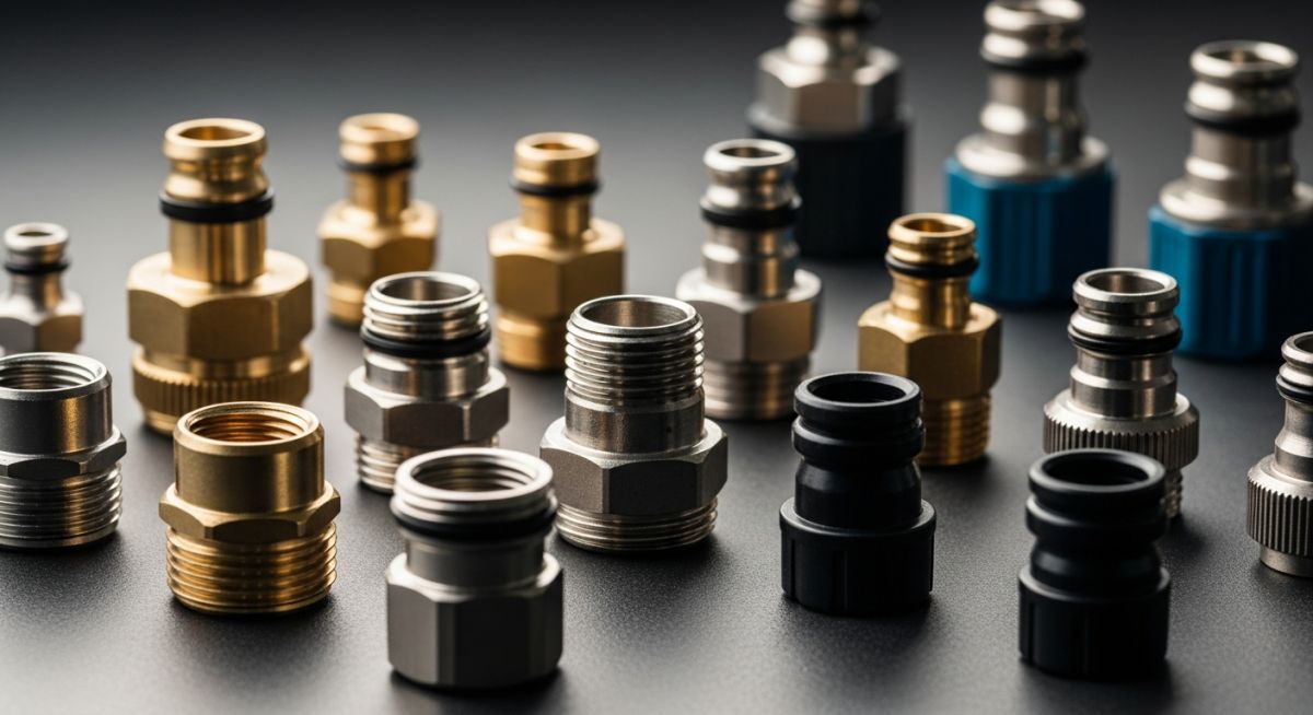
Industrial Hose Connectors: A Comprehensive Engineering Selection Guide
In my 20 years of piping engineering, I have seen minor connection failures shut down entire multi-million dollar process plants. We often spend months optimizing heavy-wall piping runs, only to treat the flexible hose assemblies as an afterthought. This is a dangerous mistake. Selecting the correct coupling interface is just as critical as sizing the main header.
Whether you are handling high-pressure hydraulic fluids, corrosive chemicals, or high-temperature steam, understanding the mechanical limits of your connection points is paramount. This guide draws on my field experience to break down the engineering principles, selection criteria, and installation practices that keep industrial fluid transfer systems operating safely and efficiently.
Key Engineering Takeaways
- Understand how temperature derating factors directly impact the maximum allowable working pressure of metallic and non-metallic couplings.
- Master the STAMPED methodology to eliminate selection errors in high-risk chemical and hydraulic applications.
- Learn to identify and mitigate the mechanical stresses caused by improper hose installation and lack of bend radius compliance.
- Discover the specific testing protocols required by ASME and NAHAD to certify hose assemblies before field commissioning.
How to Select Industrial Hose Connectors
When designing a flexible transfer system, we must look beyond simple thread matching. The connection interface must withstand dynamic mechanical forces, thermal expansion, and chemical degradation. To achieve this, I rely on the industry-standard STAMPED methodology, which stands for Size, Temperature, Application, Media, Pressure, Ends, and Delivery.
1. Pressure and Temperature Derating Calculations
A common field error is using the nominal catalog pressure rating of a connector at elevated operating temperatures. Most metallic and elastomer components lose mechanical strength as temperature rises. To calculate the actual Maximum Allowable Working Pressure (MAWP) of your assembly, you must apply a temperature derating factor.
The formula for adjusted working pressure is:
For example, if you have a 316 Stainless Steel braided hose connector rated for 1000 PSI at 70 degrees Fahrenheit, and your operating temperature is 400 degrees Fahrenheit, you must apply the derating factor for 316 SS at that temperature (typically 0.86).
Operating this system at 900 PSI at 400 degrees Fahrenheit would exceed the safe limits of the material, risking catastrophic mechanical failure.
2. Fluid Velocity and Pressure Drop Limits
Excessive fluid velocity inside a hose assembly leads to turbulent flow, localized erosion, and high pressure drops. This is especially true at the connector interface where the internal diameter often constricts.
To calculate fluid velocity, use the following formula:
In my practice, I design liquid transfer lines to keep velocities below 15 feet per second for pressure lines and below 4 feet per second for suction lines to prevent cavitation and premature wear on the connector seats.
When assembling stainless steel threaded connectors (such as NPT or BSPT), always use a high-quality nickel-based anti-seize compound or PTFE tape. Stainless steel is highly susceptible to cold welding (galling) under load. Once galling occurs, the threads lock permanently, destroying the connector and rendering the assembly useless during maintenance turnarounds.
3. Mechanical Stress and Bend Radius Compliance
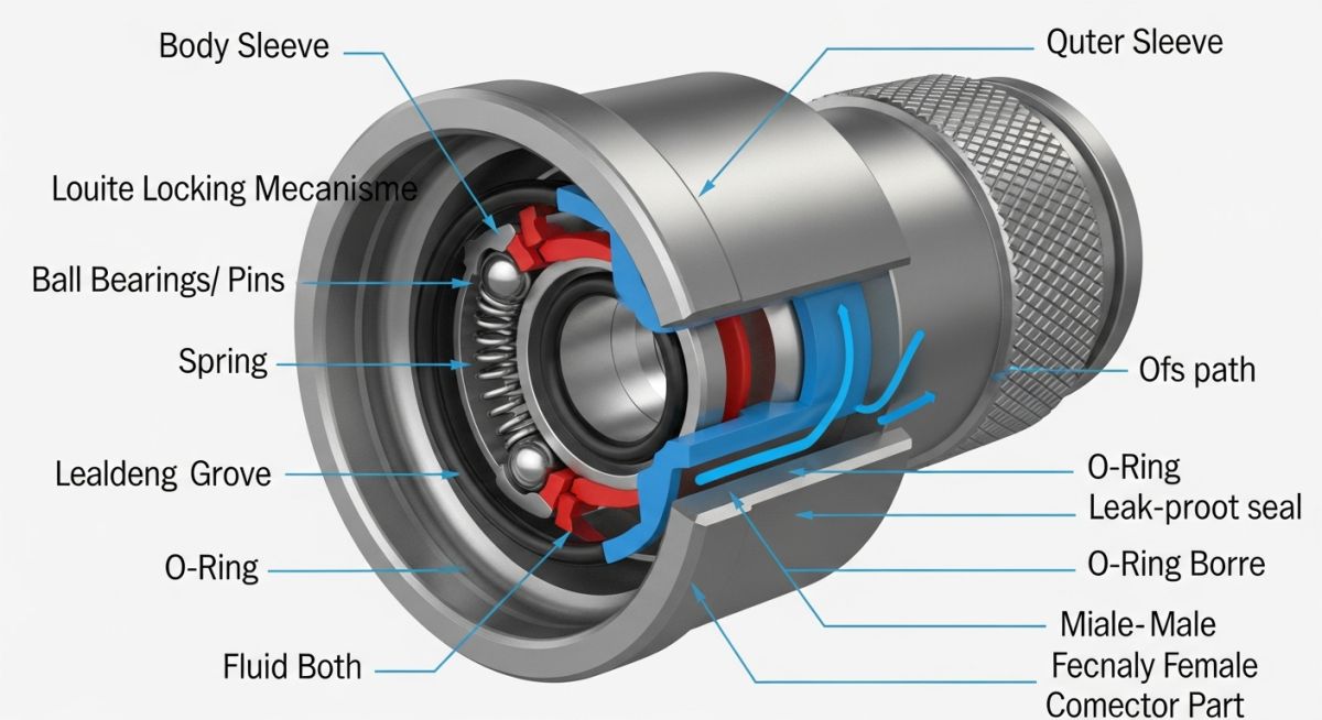
Hose connectors are rigid points in a flexible system. The transition zone between the rigid coupling and the flexible hose body is the most common failure point due to bending stress. You must ensure that the hose does not bend sharply immediately behind the coupling collar. Implementing bend restrictors or utilizing 45-degree or 90-degree elbow connectors can redirect the flow path and eliminate harmful bending moments.
The table below outlines the nominal pressure ratings and temperature limits for common industrial hose connector materials. These values are based on standard configurations and must be verified against specific manufacturer specifications and ASME B31.3 design limits.
| Material Type | Nominal Pressure (PSI) | Temp Range (Fahrenheit) | Common Applications | Applicable Standard |
|---|---|---|---|---|
| Carbon Steel (Plated) | 3,000 to 10,000 | -40 to 250 | Hydraulic systems, lube oil lines | SAE J517 |
| 316 Stainless Steel | 2,500 to 6,000 | -320 to 800 | Corrosive chemicals, high temp steam | ASME B31.3 |
| Brass (Alloy C360) | 500 to 1,500 | -40 to 400 | Water, compressed air, low-pressure gas | ASTM B16 |
| Polypropylene | 100 to 150 | 32 to 150 | Agricultural chemicals, water transfer | FDA Compliant |
This matrix maps core technical entities, structural acronyms, and physical parameters to their respective industry standards. Use this as a quick reference during the engineering design phase.
| Entity / Acronym | Full Technical Name | Primary Physical Parameter | Reference Standard |
|---|---|---|---|
| NPT | National Pipe Tapered Thread | Thread angle 60 degrees, taper 1 in 16 | ASME B1.20.1 |
| JIC | Joint Industry Council | 37-degree flare seating surface | SAE J514 |
| MAWP | Maximum Allowable Working Pressure | Hydrostatic design stress limit | ASME Section VIII |
| NAHAD | National Association of Hose and Accessories Distributors | Hose assembly safety guidelines | NAHAD Quality Guide |
Installing High Pressure Hose Connectors Safely
Before commissioning any flexible hose assembly, field technicians must perform a rigorous physical inspection. Skipping these steps can lead to premature wear, leaks, or catastrophic blowouts under pressure. I have developed this checklist over years of managing high-pressure piping installations.
Pre-Commissioning Field Checklist
-
Verify Material Compatibility: Ensure the connector material matches the chemical properties of the process fluid. Check the MTR (Material Test Report) to confirm compliance with ASTM standards.
-
Inspect Thread and Seating Surfaces: Check for nicks, burrs, or deformation on NPT, JIC, or flat-face flange surfaces. Damaged threads will not seal properly and can gall during assembly.
-
Confirm Minimum Bend Radius: Verify that the hose does not bend sharper than the manufacturer’s specified minimum bend radius immediately adjacent to the connector collar.
-
Check for Hose Twist (Torsion): Ensure the hose is not twisted during installation. Torsion under pressure significantly reduces hose life and can loosen threaded connectors. Look at the layline of the hose to ensure it is straight.
-
Apply Correct Torque: Use a calibrated torque wrench to tighten connections to the manufacturer’s specified torque values. Over-tightening can deform the connector seats, while under-tightening leads to leaks.
Field Case Study: Real-World Application
The Problem: Premature Failures in Chemical Transfer Lines
At a specialty chemical processing plant, maintenance teams reported that flexible PTFE-lined hose assemblies transferring hot sulfuric acid (98% concentration at 180 degrees Fahrenheit) were failing every three to four months. The failures consistently occurred at the crimped connector interface.
Upon physical inspection, I discovered that the plant was using standard 316 Stainless Steel crimp collars with carbon steel inserts. The high temperature was causing thermal expansion mismatches, and localized chemical attack was eating away the sealing serrations inside the collar, leading to acid weeping and eventual blowout.
The Outcome: Material Upgrade and Redesigned Interface
I recommended replacing the mixed-alloy connectors with fully integrated Hastelloy C-276 insert fittings and matching Hastelloy crimp collars. We also modified the piping layout to include a 90-degree elbow connector, reducing the mechanical bending stress on the hose transition zone.
Following these modifications, the service life of the hose assemblies extended from 4 months to over 24 months without a single recorded leak. This simple engineering change saved the plant over 80,000 annually in replacement parts and prevented hazardous chemical exposure for the operators.
My direct recommendation for any high-temperature chemical application is to perform a thorough galvanic and thermal expansion analysis of the connector components. Never mix materials with significantly different thermal expansion coefficients in dynamic thermal cycling services.
Frequently Asked Engineering Questions
What is the difference between NPT and NPSM hose connectors?
How do I determine the correct hose connector size?
Why do quick-disconnect hose connectors leak during low-pressure operations?
Can I reuse crimped hose connectors during maintenance?
What standards govern the testing of industrial hose connectors?
How does galvanic corrosion affect hose connectors?
Complete Course on
Piping Engineering
Check Now
Key Features
- 125+ Hours Content
- 500+ Recorded Lectures
- 20+ Years Exp.
- Lifetime Access
Coverage
- Codes & Standards
- Layouts & Design
- Material Eng.
- Stress Analysis
