Table of Contents
What is a Sucker Rod? Its Types and Critical Importance
In my 20 years of field engineering, I have seen many rod strings snap. When you are operating a reciprocating artificial lift system at 9,000 feet, a single mechanical failure can halt production and cost upwards of fifty thousand dollars in workover rig time. The sucker rod is the unsung hero of the oilfield, serving as the physical muscle that transmits mechanical energy from the surface pumpjack down to the subsurface plunger.
Understanding how these rods behave under continuous cyclic loading is not just a theoretical exercise. It is a fundamental requirement for optimizing well run-life and preventing catastrophic fatigue failures. In this guide, I will share my hands-on experience with sucker rod design, material selection, and field installation practices.
Key Engineering Takeaways
- Learn the mechanical differences between API Grade C, Grade D, and Grade K sucker rods.
- Understand how to calculate peak polished rod loads to prevent fatigue propagation.
- Discover why fiberglass composite rods are transforming deep-well artificial lift designs.
- Master the field installation steps required by API RP 11BR to eliminate thread failures.
What is a Sucker Rod in Oil Production?
To understand the engineering behind a sucker rod, we must look at the dynamics of the entire rod string. The string is not a rigid beam; it behaves like an incredibly long, highly elastic spring. During the upstroke, the rod string must lift the weight of the fluid column plus its own weight, which subjects the top rods to massive tensile loads. During the downstroke, the rods fall through the viscous well fluid, introducing compressive forces that can cause buckling if not managed correctly.
To calculate the loads acting on the rod string, we rely on the Peak Polished Rod Load (PPRL) formula. This calculation is critical for sizing both the surface pumping unit and the rod string itself:
Where:
– PPRL = Peak Polished Rod Load (lbs)
– Wf = Weight of fluid (lbs) = 0.433 * SG * (D * Ap – Ar)
– Wr = Weight of the rod string in air (lbs)
– alpha = Acceleration factor (dimensionless) = (N^2 * S) / 70500
– N = Pumping speed (strokes per minute)
– S = Stroke length (inches)
– SG = Specific gravity of the produced fluid
– D = Depth of the pump (feet)
– Ap = Area of the pump plunger (sq in)
– Ar = Average cross-sectional area of the rod string (sq in)
Conversely, the Minimum Polished Rod Load (MPRL) occurs during the downstroke and is calculated as:
The difference between PPRL and MPRL represents the cyclic stress range. I always use the Modified Goodman Diagram, as specified in API RP 11BR, to determine if this stress range falls within the safe operating limits of the selected steel grade.
Selecting the Best Sucker Rod for Wells
Sucker rods are classified into distinct grades by the American Petroleum Institute. Selecting the wrong grade is a costly mistake I have corrected on multiple projects. Let us break down the primary types:
1. API Grade C Sucker Rods
These rods are manufactured from carbon steel (typically AISI 1036 or equivalent). They feature a minimum tensile strength of 90,000 psi to 115,000 psi. Grade C rods are highly ductile and offer excellent resistance to mild corrosion, making them ideal for shallow, low-load wells where chemical treatment is easily maintained.
2. API Grade K Sucker Rods
Grade K rods are made from nickel-chromium alloy steel (such as AISI 4620). They have a similar tensile strength to Grade C (90,000 to 115,000 psi) but offer superior corrosion resistance. In my experience, Grade K is the absolute standard for sour wells (H2S) and carbon dioxide (CO2) flooded reservoirs where high tensile strength is not the primary design constraint.
3. API Grade D Sucker Rods
Grade D rods are crafted from high-strength carbon-manganese or chromium-molybdenum alloy steels (like AISI 4142). They boast a minimum tensile strength of 115,000 psi to 140,000 psi. These rods are designed for deep wells and heavy fluid loads. However, they are highly susceptible to sulfide stress cracking (SSC) in sour environments.
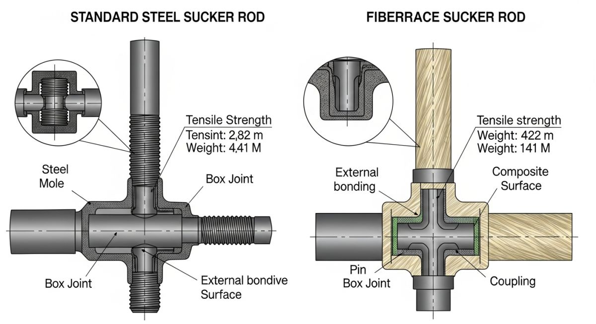
4. Fiberglass (FRP) Sucker Rods
Fiberglass rods represent a major technological leap. They consist of continuous glass fibers bound by an epoxy resin, fitted with steel end connectors. Because fiberglass is lightweight, it reduces the static load on the surface unit by up to 40%. This allows operators to use smaller pumpjacks, reduce energy consumption, and increase stroke length.
| API Grade | Material Composition | Min Tensile Strength (psi) | Max Tensile Strength (psi) | Recommended Environment |
|---|---|---|---|---|
| Grade C | Carbon Steel (AISI 1036) | 90,000 | 115,000 | Shallow, non-corrosive, or treated wells |
| Grade K | Nickel-Alloy Steel (AISI 4620) | 90,000 | 115,000 | Highly corrosive, sour (H2S) or CO2 wells |
| Grade D | Alloy Steel (AISI 4140/4142) | 115,000 | 140,000 | Deep, heavy-load, non-corrosive wells |
| Fiberglass | Glass Fiber / Epoxy Resin | 120,000 | 160,000 | Deep, high-volume, highly corrosive wells |
| Technical Entity | Acronym | Physical Parameter | Standard Reference |
|---|---|---|---|
| Peak Polished Rod Load | PPRL | Maximum tensile force at surface (lbs) | API RP 11BR |
| Minimum Polished Rod Load | MPRL | Minimum downstroke force at surface (lbs) | API RP 11BR |
| Sulfide Stress Cracking | SSC | Brittle failure mechanism under H2S exposure | NACE MR0175 |
| Fiber Reinforced Plastic | FRP | Composite material structure (psi) | API Spec 11B |
Sucker Rod Field Installation Checklist
During my time supervising well completions, I discovered that over 70% of early rod failures occur due to improper handling and makeup torque on the rig floor. If the crew does not clean the threads or over-torques the pins, the rod string is doomed before it even touches the fluid. Use this field-verified checklist to ensure your crew executes the installation flawlessly:
Pre-Running and Makeup Verification Steps
-
Visual Inspection: Check every rod body for nicks, gouges, or bending. Any rod with a surface defect deeper than 10% of the rod diameter must be rejected immediately.
-
Thread Cleaning: Remove all thread protectors and clean both pin and coupling threads using a wire brush and petroleum-based solvent. Ensure no sand or grit remains.
-
Lubrication: Apply a high-quality API-approved thread compound (do not use standard pipe dope) to the pin threads and coupling face.
-
Circumferential Displacement: Use a calibrated rod-makeup card to measure circumferential displacement. Do not rely solely on hydraulic tong pressure gauges, as they can be highly inaccurate.
-
Running Speed Control: Limit the running-in-hole (RIH) speed to prevent the rod couplings from slamming into the tubing walls, which can cause micro-fractures.
Field Case Study: Real-World Application
The Problem: Frequent Fatigue Failures in the Williston Basin
An operator in the Williston Basin was managing a deep oil well (9,200 feet) producing 350 barrels of fluid per day with a high water cut (85%) and moderate CO2 levels. The well was equipped with a full API Grade D steel sucker rod string. Due to the heavy fluid load and corrosive environment, the rod string suffered from frequent fatigue-induced parting every 45 to 60 days. This resulted in high workover costs and lost production.
The Solution: Tapered Fiberglass-Steel Redesign
I was brought in to redesign the rod string. We replaced the top 4,000 feet of the string with high-strength fiberglass sucker rods and used API Grade K rods for the bottom 5,200 feet to handle the corrosive downhole fluids. This tapered design utilized the high elasticity and lightweight nature of fiberglass at the top, while keeping the corrosion-resistant steel rods at the bottom where compressive forces occur.
The results were immediate and highly profitable. By reducing the total weight of the rod string, the Peak Polished Rod Load (PPRL) dropped from 28,500 lbs to 19,200 lbs—a 32% reduction. This allowed the operator to keep using their existing surface pumping unit without overloading the gearbox.
Most importantly, the run-life of the well extended from an average of 52 days to over 730 days without a single rod part. The payback period for the new composite rod string was achieved in just 4 months.
Frequently Asked Engineering Questions
What is the difference between a sucker rod and a pony rod?
How does hydrogen sulfide (H2S) cause sucker rod failure?
Why are fiberglass sucker rods used in deep wells?
What is the purpose of a sucker rod guide?
How is sucker rod makeup torque determined?
What is the significance of the API RP 11BR standard?
===FAQ_BLOCK===
Complete Course on
Piping Engineering
Check Now
Key Features
- 125+ Hours Content
- 500+ Recorded Lectures
- 20+ Years Exp.
- Lifetime Access
Coverage
- Codes & Standards
- Layouts & Design
- Material Eng.
- Stress Analysis

Related posts:
![Comparison of raw PTFE material and an industrial PTFE-lined steel pipe flange]()
Teflon vs PTFE: Major Differences in Industrial Piping Applications
![Severe metal galling damage on a stainless steel threaded bolt and nut.]()
What is Metal Galling and How to Prevent It
![Certified welder performing structural welding repair on a heavy steel beam with sparks flying.]()
Mastering Industrial Welding Repair Procedures for Structural Integrity
![A fully assembled industrial pump skid system with stainless steel piping and control panels in a factory.]()
What is an Industrial Pump Skid and Its Key Advantages?
![Side-by-side comparison of an industrial flow meter and a digital flow transmitter installed on a pipeline.]()
Flow Transmitter vs Flow Meter: Key Differences Explained
![Wireless vibration sensor mounted on an industrial electric motor for condition monitoring.]()
What is Vibration Monitoring and Why is it Important?