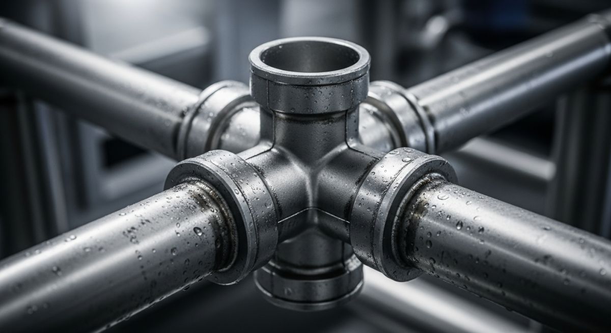
What are Pipe Cross Fittings and Why Are They Critical?
In my 20 years of designing process piping systems for chemical plants and refineries, I have often observed that the simplest-looking components present the most complex engineering challenges. The four-way cross is a prime example. While a standard tee splits a flow into two directions, a cross connects four lines at a single junction. This sounds highly efficient on paper, but in practice, it introduces unique mechanical stresses and flow dynamics that require careful calculation.
When you are dealing with high-pressure steam, corrosive chemicals, or hydraulic fluids, choosing the right fitting is not just about matching nominal pipe sizes. It is about understanding how the geometry of the fitting handles thermal expansion, pressure drops, and mechanical loads. In this guide, I will share my field experience on how to design, specify, and inspect these components to ensure long-term system reliability.
Key Engineering Takeaways
- Crosses are highly space-efficient but experience higher stress concentrations at the crotch radius compared to standard tees.
- They are governed by strict manufacturing standards, primarily ASME B16.9 for butt-welded fittings and ASME B16.11 for forged socket-weld and threaded fittings.
- Thermal expansion in multi-directional systems can generate massive bending moments on the branch connections of a cross.
- Proper support placement is mandatory to prevent fatigue failure at the intersecting joints.
How Do Pipe Cross Fittings Manage Fluid Distribution?
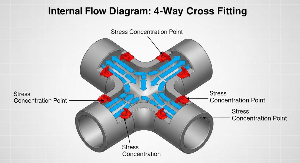
From a fluid dynamics perspective, a cross is a highly turbulent zone. When fluid enters one port and splits into three directions, or when multiple streams merge into one, the localized velocity profiles change rapidly. This rapid change in direction creates a significant pressure drop and induces localized turbulence, which can accelerate erosion-corrosion if the fluid contains suspended solids or corrosive agents.
Stress Concentration and Crotch Radius Calculations
The most critical mechanical aspect of a cross is the stress concentration at the “crotch”—the inner radius where the branch and run pipes intersect. Under internal pressure, the hoop stress in the pipe wall is interrupted by the opening. To compensate for this, the fitting must have extra wall thickness in the crotch region.
According to ASME B31.3 Section 304.3.2, the reinforcement area required for a branch connection must be calculated to ensure the fitting can withstand the design pressure. For a standard cross, we must evaluate the reinforcement on both branch openings. The formula for the required reinforcement area (A_1) is expressed as:
Where:
• th = Nominal header thickness required for pressure design.
• d1 = Effective length of the opening in the header.
• beta = Angle between the branch and header axes (90 degrees for standard crosses).
In my field audits, I have seen several cross fittings fail due to thermal expansion. Because a cross anchors four lines in a single plane, any thermal expansion in those lines will transmit massive bending moments directly to the fitting. If the piping system does not have adequate expansion loops or flexible supports, the crotch of the cross will crack, leading to catastrophic loss of containment.
Manufacturing Standards and Material Specifications
Depending on the piping class and service conditions, crosses are manufactured using different methods:
- Butt-Welding Crosses (ASME B16.9): Typically used in larger pipelines (2 inches and above) where full penetration welds are required for high-pressure or hazardous services. These are seamless or welded wrought fittings.
- Forged Socket-Welding and Threaded Crosses (ASME B16.11): Used for small-bore piping (2 inches and smaller). Socket welds provide a leak-tight joint, while threaded connections are reserved for utility lines, low-pressure water, or non-hazardous fluids.
Selecting the Right Pipe Cross Fittings for Systems
To assist piping designers in selecting the correct dimensions for butt-welding crosses, the table below outlines the standard dimensions for straight crosses in accordance with ASME B16.9. Note that the center-to-end dimension (C) is identical for all four outlets on a straight cross.
| Nominal Pipe Size (NPS) | Outside Diameter at Bevel (OD – mm) | Center-to-End Dimension (C – mm) | Common Wall Schedules |
|---|---|---|---|
| 2″ | 60.3 | 64 | Sch 40, Sch 80, Sch XS |
| 3″ | 88.9 | 86 | Sch 40, Sch 80, Sch XS |
| 4″ | 114.3 | 105 | Sch 40, Sch 80, Sch 120 |
| 6″ | 168.3 | 143 | Sch 40, Sch 80, Sch 160 |
| 8″ | 219.1 | 178 | Sch 40, Sch 80, Sch XXS |
This matrix maps material grades, pressure ratings, and typical industrial applications for cross fittings. It serves as a quick reference for selecting the correct material class based on process conditions.
| Material Standard | Common Grade | Pressure Rating / Class | Typical Process Application |
|---|---|---|---|
| ASTM A105 | Carbon Steel | Class 3000 / 6000 (Forged) | High-pressure steam, non-corrosive hydrocarbons |
| ASTM A182 | F316L Stainless Steel | Class 3000 / 6000 (Forged) | Corrosive chemicals, acidic environments, food processing |
| ASTM A234 | WPB Carbon Steel | Matches Pipe Schedule (Butt-Weld) | General utility lines, cooling water, oil and gas transport |
| ASTM A403 | WP304L / WP316L | Matches Pipe Schedule (Butt-Weld) | Chemical processing, cryogenic services, marine piping |
How to Inspect Pipe Cross Fittings on Site
Before any cross fitting is welded or threaded into a piping system, it must undergo a rigorous quality control check. Because crosses are subject to high stress, any manufacturing defect or material non-conformance can lead to premature failure. Use this checklist during your next field inspection.
Site Verification Checkpoints
-
Material Test Report (MTR) Verification: Match the heat number stamped on the cross fitting with the MTR to verify chemical composition and mechanical properties.
-
Visual Crotch Inspection: Inspect the inner crotch radius for any surface cracks, laminations, or forging laps using Liquid Penetrant Testing (PT) or Magnetic Particle Testing (MT).
-
Dimensional Tolerance Check: Measure the center-to-end dimensions of all four ports. Ensure they are within the +/- 2mm tolerance specified by ASME B16.9.
-
Wall Thickness Verification: Use an ultrasonic thickness gauge to verify that the wall thickness at the crotch and the weld bevels matches the specified schedule.
-
Alignment and Fit-Up: Ensure the intersecting pipes are perfectly aligned. Forcing a pipe into a cross fitting introduces high residual stresses that will compromise the joint.
Field Case Study: Real-World Application
The Problem: Crotch Cracking in Solvent Line
At a chemical processing plant in Texas, a 6-inch ASTM A403 WP316L cross fitting was installed in a solvent recovery line operating at 180°C and 15 bar. After 14 months of operation, operators detected a solvent leak. Upon inspection, we discovered a 45mm crack propagating along the crotch radius of the cross. The system was subjected to cyclic thermal loading as the process cycled twice daily. The original design had not accounted for the high bending moments exerted on the branch lines, which acted as rigid anchors.
The Outcome: Redesign and Stress Mitigation
We conducted a Finite Element Analysis (FEA) of the joint. The analysis showed that the stress at the crotch exceeded the allowable fatigue limit of the material. To resolve this, we replaced the standard cross with a forged ASME B16.9 heavy-wall cross. We also modified the piping layout by installing expansion loops on the two branch lines and replacing the rigid pipe supports near the cross with spring hangers. This allowed the piping to expand freely, reducing the bending moment on the cross by 62%. The system has now been operating for over four years without any signs of stress cracking.
My recommendation from this event is clear: never treat a cross fitting as a simple junction. If your system undergoes temperature fluctuations of more than 50°C, you must perform a formal flexibility analysis to ensure the fitting is not overloaded.
Frequently Asked Engineering Questions
Why are cross fittings rarely used in high-pressure process piping?
What is the difference between a straight cross and a reducing cross?
Which ASME standards govern the design of cross fittings?
How do you support a piping system containing a cross fitting?
Can cross fittings be used in sanitary or hygienic piping?
What are the primary failure modes of a pipe cross?
===FAQ_BLOCK===
Complete Course on
Piping Engineering
Check Now
Key Features
- 125+ Hours Content
- 500+ Recorded Lectures
- 20+ Years Exp.
- Lifetime Access
Coverage
- Codes & Standards
- Layouts & Design
- Material Eng.
- Stress Analysis

📚 Recommended Resources: pipe cross fittings
Read these Guides
- 📄 Industrial PVC Piping and Fittings: Applications, Standards, and Support Spans
- 📄 Various Types of Pipe Clamps for Piping and Plumbing Industry
- 📄 Ductile Iron Pipe Dimensions – Global Standards, Field Challenges & Engineering Insights
- 📄 Introduction to FRP Pipes: Properties, Applications, Specifications, Codes, Joining & More


Related posts:
![Professional surveyor conducting Topographical Surveys for Solar Projects on a large-scale utility site with complex terrain.]()
Topographical Surveys for Solar Projects: A Technical Engineering Guide
![A geotechnical drill rig performing soil sampling on a large, open field intended for a utility-scale solar farm project.]()
Geotechnical Investigation for Solar Farms: Essential Site Design Guide
![Isometric site plan showing Utility Corridor Planning for Data Centres with color-coded power, water, and telecom infrastructure paths.]()
Utility Corridor Planning for Data Centres: A Strategic Engineering Guide
![Aerial view of a data centre site showcasing perimeter drainage systems, detention basins, and site grading for flood prevention.]()
Drainage Design Considerations for Data Centres: A Technical Guide
![Professional surveyor using a Total Station on a large data centre construction site for topographical mapping.]()
Topographical Surveys for Data Centre Projects: A Technical Guide
![Cross-section diagram showing Ground Improvement for Data Centres using stone columns and deep soil mixing beneath a concrete foundation slab.]()
Ground Improvement for Data Centres: Engineering Stability and Settlement Control