What Are API Flanges? | API Flange Charts and Dimensions
In my 20 years of managing piping systems in the North Sea and the Middle East, I have seen many engineers struggle when transitioning from standard refinery piping to upstream wellhead systems. The immediate point of confusion is almost always the flange design. While downstream systems rely on familiar standards, upstream oil and gas operations demand a completely different beast.
When you step onto a drilling rig or a production platform, you are no longer dealing with moderate pressures. You are managing raw, unrefined hydrocarbons at pressures that can easily exceed 10,000 psi, often accompanied by highly corrosive hydrogen sulfide and carbon dioxide. This is where standard piping components fail, and where specialized high-pressure connectors become the baseline for safety and operational integrity.
What You Will Learn in This Guide:
- The fundamental design differences between API and ASME flange standards.
- How to read and apply API flange dimension charts for field installations.
- The critical role of metal-to-metal ring joint gaskets in high-pressure sealing.
- Practical field inspection protocols to prevent catastrophic wellhead leaks.
Why Do We Use API Flanges in Oilfields?
To understand these components, we must look at the governing standard: API Specification 6A (Specification for Wellhead and Christmas Tree Equipment). This standard is fundamentally different from ASME B16.5, which governs flanges used in process piping.
While ASME flanges are categorized by pressure classes (such as Class 150, 300, 600, 900, 1500, and 2500), API flanges are categorized by their maximum working pressure ratings: 2000, 3000, 5000, 10000, 15000, and 20000 psi. The material requirements for API components are also significantly more stringent, requiring high-yield strength steels that can handle sour service (H2S) as specified by NACE MR0175.
The Mechanics of the Metal-to-Metal Seal
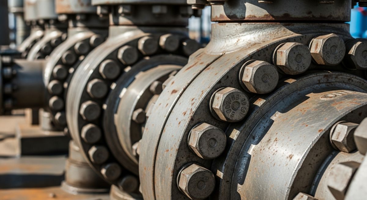
Unlike ASME raised-face flanges that often use elastomeric or spiral-wound gaskets, API designs rely entirely on metal-to-metal seals. The flange face features a highly machined ring groove designed to accept a solid metal ring joint gasket (RTJ).
As the bolt studs are tensioned, the ring gasket is deformed into the groove. This plastic deformation creates an incredibly tight, gas-tight seal. In my experience, the choice of ring gasket is just as critical as the flange itself. The three primary types used are:
- Type R (Oval or Octagonal): The classic design used in older systems and lower pressure ratings (up to 5000 psi). It provides a reliable seal but is not pressure-energized.
- Type RX: A pressure-energized variation of the Type R. The outer sealing face makes contact first, and internal line pressure forces the gasket outward against the groove, improving the seal as pressure increases.
- Type BX: Designed exclusively for high-pressure systems (10000 to 20000 psi). These gaskets feature a pressure balance hole to equalize pressure across the sealing faces, preventing pressure trapping.
Never assume that matching bolt patterns mean compatible pressure ratings. For example, a 2-1/16 inch API 2000 flange shares the exact same bolt circle and bolt hole diameter as a 2-inch ASME Class 600 flange. However, the API flange is significantly thicker and designed for much higher yield strengths. Attempting to bolt these mismatched standards together in the field can lead to catastrophic joint failure under pressure.
Understanding Flange Design Calculations
The structural integrity of an API connection depends on maintaining sufficient bolt preload to resist the separation forces caused by internal pressure. The design bolt load must overcome the hydrostatic end force while maintaining enough gasket seating stress to prevent leakage.
In engineering terms, the total design bolt load is calculated by taking the design pressure and multiplying it by the area of the gasket reaction circle, then adding the product of the gasket contact width, the gasket pitch diameter, the gasket factor, and the design pressure. This calculation ensures that even under maximum test pressures (which are typically 1.5 times the working pressure), the flange face does not separate.
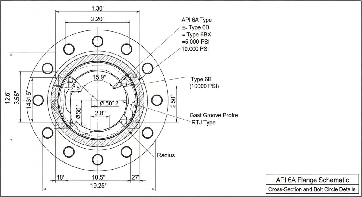
The table below provides critical engineering dimensions for Type 6B flanges, which are standard for pressures up to 5000 psi. These dimensions must be verified during the design phase and checked on-site before assembly.
| Nominal Size (in) | Working Pressure (psi) | Flange OD (in) | Bolt Circle (in) | Number of Bolts | Bolt Diameter (in) | Ring Gasket No. |
|---|---|---|---|---|---|---|
| 2-1/16 | 2000 | 6.50 | 5.00 | 8 | 5/8 | R-23 or RX-23 |
| 2-1/16 | 3000 | 8.50 | 6.50 | 8 | 7/8 | R-24 or RX-24 |
| 2-1/16 | 5000 | 8.50 | 6.50 | 8 | 7/8 | RX-24 |
| 3-1/8 | 2000 | 8.25 | 6.62 | 8 | 3/4 | R-31 or RX-31 |
| 3-1/8 | 3000 | 9.50 | 7.50 | 8 | 7/8 | R-35 or RX-35 |
| 3-1/8 | 5000 | 10.62 | 8.00 | 8 | 1-1/8 | RX-35 |
This matrix maps key technical entities, structural acronyms, and physical parameters to their governing standards and typical field applications.
| Entity / Acronym | Technical Definition | Governing Standard | Primary Application |
|---|---|---|---|
| Type 6B | Ring-joint flanges that are not designed for face-to-face make-up. The sealing force reacts on the metallic ring gasket. | API 6A | Low to medium pressure wellheads (2000 to 5000 psi). |
| Type 6BX | Ring-joint flanges designed with a raised face that allows face-to-face contact when fully torqued, protecting the gasket from over-compression. | API 6A | High-pressure wellheads and manifolds (10000 to 20000 psi). |
| NACE MR0175 | Standard specifying material requirements for resistance to sulfide stress cracking in sour oilfield environments. | NACE / ISO 15156 | Material selection for wet H2S-containing production. |
| RTJ Groove | A highly machined, close-tolerance groove on the flange face designed to house the metallic ring gasket. | ASME B16.20 / API 6A | High-pressure and high-temperature sealing interfaces. |
How to Inspect API Flanges on Site
Before any high-pressure system is pressurized, a rigorous physical inspection must be conducted. In my years of field supervision, I have found that skipping even a single step on this list can lead to costly downtime or severe safety incidents during pressure testing.
Field Inspection Checkpoints:
-
Verify Ring Groove Surface Finish: Inspect the sealing surfaces of the groove for any scratches, tool marks, or pitting. The surface roughness must not exceed 63 micro-inches (1.6 micrometers) for Type 6B flanges.
-
Confirm Gasket Hardness: Ensure the ring joint gasket is softer than the flange material. For example, a soft iron gasket (maximum 90 HB) or low carbon steel gasket (maximum 120 HB) must be used with standard carbon steel flanges to ensure proper plastic deformation.
-
Check Flange Alignment and Parallelism: Flange faces must be parallel within 0.5 millimeters per meter of flange diameter. Bolt holes must align perfectly to prevent bending stresses on the studs.
-
Validate Bolt Torque Specifications: Ensure that all studs are lubricated with an approved anti-seize compound and torqued in a star pattern. Torque values must match the engineering design sheet, which is typically based on API 6A Annex D guidelines.
-
Inspect Vent Holes on BX Flanges: For Type 6BX flanges, verify that the vent hole in the BX gasket is clear of debris. This hole is critical for preventing pressure lock during assembly.
Field Case Study: Real-World Application
The Problem: High-Pressure Gas Leak During Well Testing
During the commissioning of a high-pressure gas manifold in the Permian Basin, a severe gas leak was detected at a 3-1/8 inch API 10000 flange connection. The system was operating at approximately 8,500 psi when the gas detector triggered an alarm.
Upon depressurizing and dismantling the joint, the field crew discovered that a standard R-35 octagonal gasket had been installed instead of the specified pressure-energized BX-154 gasket. The flange groove was also found to have minor scoring from previous assembly attempts, which compromised the metal-to-metal seal.
The Outcome: Corrective Action and Pressure Containment
I was called to the site to supervise the remediation. We immediately rejected the damaged flange and had the face re-machined on-site using a portable flange facing machine to restore the groove surface finish to 32 micro-inches.
We then sourced a certified, low-carbon steel BX-154 gasket. The studs were replaced with new ASTM A193 Grade B7M bolts to ensure resistance to sour gas. The joint was assembled using a hydraulic torque wrench, applying torque in four progressive stages (30%, 60%, 100%, and a final circular check) to ensure even gasket seating.
The system was successfully pressure tested to 15,000 psi (1.5 times the working pressure) for 4 hours with zero pressure drop, proving the integrity of the restored metal-to-metal seal.
This case highlights why strict adherence to API 6A specifications is not optional. A simple gasket mix-up or a minor scratch in the ring groove can lead to a catastrophic release of high-pressure hydrocarbons, risking lives and causing massive environmental damage.
Common Questions About API Flanges
What is the main difference between ASME and API flanges?
Can you bolt an ASME flange to an API flange?
What is the difference between Type 6B and Type 6BX flanges?
Why do BX gaskets have a hole drilled through them?
What materials are used for API 6A flanges?
How often should API flange gaskets be replaced?
===
Complete Course on
Piping Engineering
Check Now
Key Features
- 125+ Hours Content
- 500+ Recorded Lectures
- 20+ Years Exp.
- Lifetime Access
Coverage
- Codes & Standards
- Layouts & Design
- Material Eng.
- Stress Analysis