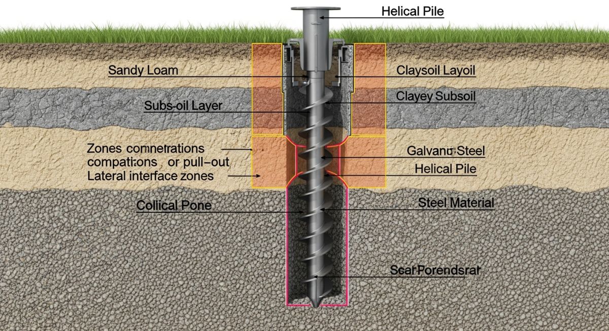
Geotechnical Risks in Solar Projects: A Structural Engineering Perspective
In my two decades of experience overseeing large-scale energy infrastructure, I have observed that the most common point of failure for utility-scale solar arrays is not the PV module itself, but the interface between the racking system and the earth. Geotechnical risks in solar projects are frequently underestimated during the initial feasibility phase, leading to catastrophic differential settlement or premature foundation corrosion.
When we ignore the nuances of soil mechanics—such as expansive clay behavior or high-salinity groundwater—we invite structural instability that can compromise the entire array’s wind-load capacity. This guide provides the technical rigor required to assess these risks before the first pile is driven.
Key Takeaways for Project Success
- Conduct site-specific soil resistivity testing to prevent accelerated foundation corrosion.
- Implement rigorous pull-out and lateral load testing to validate pile design assumptions.
- Account for seasonal moisture fluctuations in expansive soil zones to prevent racking misalignment.
- Integrate geotechnical data directly into the structural racking design software for accurate stress modeling.
Analyzing Geotechnical Risks in Solar Projects
Geotechnical Risks in Solar Projects: The comprehensive evaluation of soil-structure interaction parameters, including bearing capacity, shear strength, and chemical corrosivity, to ensure foundation stability under dynamic wind and snow loads.
The structural integrity of a solar array relies on the foundation’s ability to resist vertical, lateral, and moment loads. In my experience, the primary challenge is the variability of soil profiles across large sites. We must utilize ASTM D1586 standard penetration testing to establish a baseline for soil density and consistency.
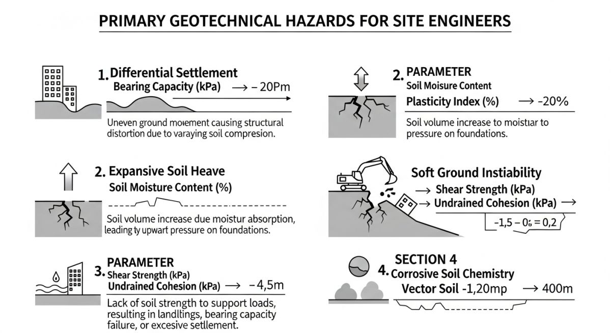
Differential Settlement and Load Distribution
Differential settlement occurs when the soil beneath a racking row compresses unevenly. This is particularly prevalent in sites with heterogeneous fill or varying moisture content. If the settlement exceeds the tolerance of the racking system—typically measured in millimeters—the structural connections experience secondary stresses that can lead to bolt shear or frame buckling.
To calculate the allowable bearing pressure, we apply the Terzaghi bearing capacity equation, adjusting for the shape and depth of the pile foundation. For driven piles, the skin friction component is the dominant factor in load resistance. We must verify this through field load testing, ensuring the factor of safety meets the requirements set forth in ASCE 7 for wind-induced uplift.
Field Warning: Expansive Soil Hazards
In regions with high plasticity index clays, moisture-induced volume changes can exert significant uplift forces on piles. These forces often exceed the dead weight of the racking system, causing the piles to “heave” out of the ground. Always specify a minimum embedment depth below the active zone of moisture fluctuation to mitigate this risk.
Corrosion and Chemical Degradation
Corrosion is a silent killer in solar projects. High chloride or sulfate concentrations in the soil, combined with low resistivity, create an electrolytic environment that rapidly degrades galvanized steel piles. I mandate soil resistivity testing at multiple depths to determine the appropriate coating thickness or material selection, such as stainless steel or high-density polyethylene (HDPE) sleeves.
Referencing NACE International standards, we categorize soil corrosivity based on resistivity values. Soils with resistivity below 1,000 ohm-cm are considered highly corrosive, requiring cathodic protection or increased sacrificial steel thickness. Neglecting these parameters leads to a reduction in the effective cross-sectional area of the pile, drastically lowering the buckling capacity of the foundation.
Geotechnical Risk Mitigation: The strategic application of soil stabilization and foundation design techniques to minimize long-term structural maintenance and maximize the operational lifespan of solar assets.
Advantages of Rigorous Geotechnical Analysis
- Optimized pile embedment depths reduce material costs and installation time.
- Early identification of corrosive soils prevents premature foundation failure and costly retrofits.
- Accurate soil data allows for precise wind-load modeling, enhancing structural safety.
- Reduced risk of differential settlement ensures consistent tracking system alignment.
- Improved site drainage planning prevents long-term soil saturation and loss of shear strength.
Disadvantages of Inadequate Geotechnical Assessment
- Underestimated soil loads lead to structural failure during extreme weather events.
- Unexpected subsurface obstructions cause significant project delays and equipment damage.
- Corrosion-related failures necessitate expensive, complex foundation replacement programs.
- Inaccurate bearing capacity assumptions result in excessive pile settlement.
- Increased insurance premiums and liability risks due to poor site characterization.
Geotechnical Engineering Applications: The practical deployment of soil mechanics principles across diverse solar project environments to ensure structural resilience and long-term performance.
Utility-Scale Desert Installations
In arid environments, the primary geotechnical challenge is the presence of loose, cohesionless sands and potential for wind-driven erosion. We utilize deep-driven piles with specialized friction-enhancing coatings to ensure stability against high-velocity wind loads, while implementing site-wide dust suppression to maintain soil moisture consistency.
Brownfield Solar Redevelopment
Redeveloping former industrial sites requires rigorous soil contamination testing alongside geotechnical analysis. We often employ shallow concrete ballast foundations instead of driven piles to avoid disturbing potentially hazardous subsurface layers, ensuring the structural load is distributed over a wider surface area to prevent settlement.
Coastal and High-Salinity Sites
Coastal solar projects face extreme corrosion risks due to salt-laden air and saline groundwater. We specify high-grade stainless steel or hot-dip galvanized piles with additional epoxy coatings, coupled with cathodic protection systems to neutralize the electrolytic potential of the soil, ensuring the foundation remains intact for the 25-year project life.
Agricultural Land Conversion
Converting farmland to solar arrays often involves dealing with high-organic-content soils and complex drainage patterns. We perform extensive shear strength testing to ensure the soil can support the racking system without excessive deformation, often incorporating geotextile reinforcement to stabilize the ground surface and prevent erosion around pile bases.
In my two decades of experience, the primary failure mode for utility-scale solar arrays is not the structural steel itself, but the interaction between the foundation and the subsurface soil. When evaluating site suitability, engineers must categorize soil behavior based on standardized testing protocols to ensure the long-term stability of tracker systems and fixed-tilt racks. The following table outlines critical geotechnical parameters that dictate foundation selection, such as driven piles, helical piers, or ballasted systems.
These values represent typical thresholds derived from ASTM D2487 classification standards. When site-specific data falls outside these ranges, I strongly recommend performing additional shear strength testing or soil resistivity analysis to prevent premature structural degradation. Always cross-reference these metrics with the project-specific ASCE 7 wind and seismic load requirements to ensure the foundation can withstand lateral forces without excessive deflection.
| Soil Classification | Allowable Bearing (kPa) | Corrosivity Potential | Foundation Recommendation |
|---|---|---|---|
| Loose Sand / Silt | 50 – 100 | Low | Helical Piers |
| Stiff Clay | 100 – 200 | Moderate | Driven Piles |
| Expansive Soil | Variable | High | Deep Foundations / Ballast |
Effective project management in renewable energy requires a clear understanding of the relationship between soil mechanics, structural integrity, and environmental compliance. This matrix maps the core technical entities encountered during the geotechnical investigation phase to their respective industry standards and physical performance indicators. By aligning these variables early in the design cycle, we can significantly reduce the risk of change orders during the construction phase.
The following mapping is essential for cross-disciplinary teams, including civil engineers, structural designers, and site surveyors. Each entity listed is governed by specific testing protocols that define the safety factors required for solar racking systems. I have found that maintaining this matrix as a living document throughout the project lifecycle ensures that any changes in site conditions are immediately reflected in the foundation design strategy, thereby maintaining compliance with ISO and ASTM guidelines.
| Entity | Standard Reference | Key Parameter |
|---|---|---|
| Soil Resistivity | ASTM G57 | Ohm-cm |
| Shear Strength | ASTM D3080 | Cohesion (c) |
| Plasticity Index | ASTM D4318 | Expansion Potential |
Before mobilizing heavy equipment for pile driving or foundation installation, a rigorous site verification process is mandatory. In my experience, skipping these steps leads to catastrophic alignment issues in tracker rows, which can cause motor burnout and structural fatigue over time. Use this checklist to validate that your site conditions align with the geotechnical report and the structural design assumptions.
-
Soil Resistivity Mapping: Verify that the soil resistivity values match the grounding design requirements per IEEE 81 standards to ensure safe electrical fault dissipation. -
Groundwater Table Depth: Confirm the seasonal high-water table level. If the water table is within 1.5 meters of the surface, evaluate the risk of liquefaction or pile buoyancy. -
Slope Stability Analysis: For sites with gradients exceeding 5 percent, ensure that the geotechnical report includes a slope stability factor of safety calculation under saturated conditions. -
Corrosion Testing: Perform chemical analysis for pH, sulfates, and chlorides. If values exceed thresholds, specify galvanized steel or cathodic protection systems. -
Load Testing: Conduct at least three sacrificial pile load tests (compression and lateral) to validate the design capacity against the actual site soil profile.
Always document the results of these tests in a centralized project database. If any parameter deviates by more than 10 percent from the initial geotechnical report, pause construction and re-evaluate the foundation design. This proactive approach prevents costly retrofits and ensures the long-term bankability of the solar asset.
Problem: Unexpected Differential Settlement in a 50MW PV Array
During the commissioning phase of a large-scale solar project, we observed significant misalignment in the tracker rows, leading to binding in the drive shafts.
- Inadequate soil compaction testing during the site preparation phase.
- Presence of undocumented organic lenses in the subsurface soil profile.
- Heavy rainfall events causing localized saturation and loss of soil shear strength.
- Foundation piles were driven to a depth that did not reach the competent bearing stratum.
Outcome: Successful Remediation and Structural Stabilization
We implemented a targeted remediation strategy that restored the structural integrity of the array and prevented further downtime.
- Installed additional helical piers to bypass the soft organic soil layers.
- Implemented a rigorous drainage improvement plan to divert surface water away from the array rows.
- Adjusted the tracker control software to compensate for minor structural deviations.
- Established a long-term monitoring program using tilt sensors to track future settlement.
My recommendation for future projects is to conduct a more granular geotechnical survey, specifically targeting areas with high moisture content. Relying on regional averages is insufficient for utility-scale projects where even minor settlement can lead to significant operational losses.
How do I determine the required pile embedment depth?
- Perform standard penetration tests to determine the N-value of the soil.
- Calculate the lateral load capacity using the p-y curve method for soil-structure interaction.
- Ensure the pile reaches a depth that provides sufficient resistance against frost heave and seasonal moisture changes.
- Always validate the theoretical depth with field-based pile load testing before full-scale installation.
What are the primary indicators of expansive soil risks?
- Check the Plasticity Index (PI) using ASTM D4318; a PI greater than 25 is a strong indicator of high expansion potential.
- Observe the site for surface cracking during dry seasons, which suggests high clay content.
- Review regional geological maps for known expansive clay formations.
- Consider using moisture barriers or deep foundations that anchor below the active zone of moisture fluctuation.
How does soil corrosivity affect foundation longevity?
- Measure soil resistivity; values below 2000 ohm-cm are highly corrosive.
- Analyze pH levels; acidic soils (pH below 5.5) significantly accelerate the oxidation of carbon steel.
- Check for sulfate and chloride concentrations, which can degrade concrete foundations and steel coatings.
- Specify hot-dip galvanization or sacrificial anodes if the site environment is classified as aggressive.
What is the role of slope stability in solar design?
- Calculate the Factor of Safety (FoS) for the slope under both static and seismic conditions.
- Ensure that the foundation design accounts for the lateral soil pressure exerted by the slope.
- Implement erosion control measures such as hydroseeding or retaining walls to stabilize the surface.
- Avoid placing heavy equipment or stockpiles at the crest of a slope during construction.
When should I use ballasted foundations instead of piles?
- Use ballasted systems when the soil is too soft to provide adequate lateral resistance for piles.
- Consider ballast when the site has a high density of underground utilities that prevent deep excavation.
- Evaluate the cost-benefit ratio, as ballasted systems require significant concrete or steel weight to resist wind uplift.
- Ensure the site surface is leveled and compacted to prevent uneven settlement of the ballast blocks.
How do I mitigate the risk of soil liquefaction?
- Perform a seismic hazard analysis to determine the peak ground acceleration (PGA) for the site.
- Use ground improvement techniques like vibro-compaction or stone columns to densify the soil.
- Design foundations to extend through the liquefiable layer into a competent, non-liquefiable stratum.
- Consult with a geotechnical engineer to perform a site-specific liquefaction potential index (LPI) assessment.
Complete Course on
Piping Engineering
Check Now
Key Features
- 125+ Hours Content
- 500+ Recorded Lectures
- 20+ Years Exp.
- Lifetime Access
Coverage
- Codes & Standards
- Layouts & Design
- Material Eng.
- Stress Analysis

📚 Recommended Resources: Geotechnical Risks in Solar Projects
Read these Guides
- 📄 Drainage Design for Utility-Scale Solar Projects: Engineering Best Practices
- 📄 Essential Geotechnical Pile Design Data for Utility-Scale Solar Structures
- 📄 Topographical Surveys for Solar Projects: A Technical Engineering Guide
- 📄 Geotechnical Investigation for Solar Farms: Essential Site Design Guide