Survey Instruments Used in Geotechnical Investigations
In my two decades of experience managing large-scale industrial infrastructure projects, I have learned that the integrity of any foundation—whether for a high-pressure piping rack or a massive storage tank—rests entirely on the quality of the initial site characterization. We cannot design what we do not understand, and the subsurface environment is notoriously unpredictable.
This guide explores the essential survey instruments used in geotechnical investigations, from the heavy-duty drilling rigs that penetrate deep into the crust to the precision sensors used for in-situ testing. Understanding how these tools function is not just for the geotechnical engineer; it is a requirement for any piping or structural engineer who needs to interpret soil reports to mitigate settlement risks.
Key Takeaways for Engineers:
- Mastering the selection of drilling rigs based on soil profile and depth requirements.
- Understanding the correlation between SPT blow counts and soil bearing capacity.
- Recognizing the limitations of CPT data in gravelly or boulder-rich strata.
- Integrating geophysical survey data to bridge gaps between discrete borehole samples.
Survey Instruments Used in Geotechnical Investigations
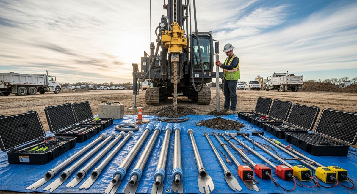
Geotechnical Investigation Instrumentation: These systems provide the empirical data required to determine soil shear strength, compressibility, and hydraulic conductivity, adhering to ASTM D1586 for penetration testing.
The foundation of any successful geotechnical campaign lies in the selection of the correct drilling rig. For most industrial applications, truck-mounted rotary rigs are the workhorses. These rigs utilize hydraulic feed systems to apply downward force (crowd) and torque to the drill string. When selecting a rig, I always evaluate the required depth of investigation and the expected soil hardness. A rig that lacks sufficient torque will struggle in dense glacial till, leading to excessive downtime and poor sample recovery.
Standard Penetration Testing (SPT) Equipment
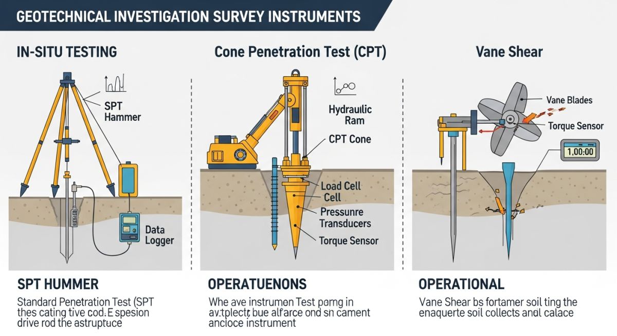
The SPT is perhaps the most ubiquitous test in our industry. It involves driving a split-spoon sampler into the soil using a 140-pound hammer falling from a height of 30 inches. The number of blows required to drive the sampler 12 inches is the N-value. In my experience, the transition from manual cathead-and-rope systems to automatic hammers has significantly improved the repeatability of these results.
Field Warning: Energy Efficiency Matters
Always verify the energy efficiency ratio of the SPT hammer. If the hammer delivers only 60% of the theoretical potential energy, your N-values will be artificially high, leading to an overestimation of soil bearing capacity and potential foundation failure.
Cone Penetration Testing (CPT) Systems
CPT provides a continuous profile of soil stratigraphy, which is a massive advantage over the discrete sampling of SPT. The CPT probe measures tip resistance, sleeve friction, and pore water pressure simultaneously. This allows us to identify thin, weak layers that a standard borehole might miss entirely. However, CPT is limited by the refusal depth in very dense or rocky soils, where the probe can be damaged.
When interpreting CPT data, we look for the friction ratio, which is the ratio of sleeve friction to tip resistance. This value is a primary indicator of soil type—clays typically exhibit higher friction ratios than sands. For deep foundation design, I rely on CPT data to estimate pile skin friction and end-bearing capacity with much higher precision than SPT-based empirical correlations.
Geotechnical Instrument Performance: Evaluating the operational trade-offs between invasive sampling methods and non-destructive geophysical techniques for site characterization.
Advantages
- SPT provides physical samples for laboratory classification and index testing.
- CPT offers high-resolution, continuous data profiles for precise stratigraphy.
- Geophysical methods cover large areas quickly without site disturbance.
- Vane shear tests provide accurate undrained shear strength in soft clays.
- Modern rigs allow for multi-purpose drilling and in-situ testing.
Disadvantages
- SPT results are highly dependent on operator technique and hammer efficiency.
- CPT probes are prone to damage in soils containing boulders or gravel.
- Geophysical data requires complex inversion and site-specific calibration.
- Vane shear is limited to soft-to-firm cohesive soils only.
- High mobilization costs for heavy drilling rigs on remote sites.
Geotechnical Investigation Deployment: Applying specialized survey instrumentation to solve complex foundation and stability challenges in diverse industrial environments.
Heavy Industrial Foundation Design
For large-scale compressor stations or turbine foundations, we utilize deep rotary drilling to extract core samples for rock mass rating (RMR) analysis. This ensures that the vibration-sensitive equipment is anchored into competent strata, preventing differential settlement that could misalign rotating machinery.
Pipeline Route Geotechnical Assessment
CPT is the preferred tool for cross-country pipeline projects where we need to identify liquefaction-prone zones or soft alluvial deposits. By deploying CPT rigs along the proposed right-of-way, we can optimize the pipeline wall thickness and burial depth to account for soil-structure interaction during seismic events.
Offshore Platform Site Characterization
In marine environments, we use specialized seabed CPT rigs to assess the upper layers of the seafloor for jacket foundation design. These instruments must withstand high hydrostatic pressures and provide real-time data to the surface vessel, allowing for immediate adjustments to the investigation plan based on the observed soil resistance.
Selecting the correct instrumentation for a geotechnical campaign requires a rigorous understanding of the operational limits defined by ASTM International standards. The table below outlines the primary performance metrics for standard equipment used in soil characterization, focusing on energy ratios, penetration rates, and typical depth capacities encountered in civil infrastructure projects.
Engineers must verify that the equipment calibration certificates are current, particularly for dynamic testing tools like the Standard Penetration Test (SPT) hammers. Variations in energy transfer efficiency can lead to significant discrepancies in N-value interpretation, potentially compromising the integrity of foundation design parameters. Always cross-reference these specifications with the specific site geology and the required depth of investigation to ensure the rig capacity is sufficient for the anticipated overburden pressures.
| Equipment Type | Standard Reference | Primary Metric | Typical Capacity |
|---|---|---|---|
| SPT Hammer | ASTM D1586 | Energy Ratio (ER) | 60% to 90% |
| CPT Cone | ASTM D5778 | Tip Resistance (qc) | Up to 100 MPa |
| Vane Shear | ASTM D2573 | Undrained Shear Strength | 0 to 200 kPa |
The following matrix provides a structured overview of the technical entities and physical parameters governing modern geotechnical site investigations. By mapping these variables to their respective testing methodologies, engineers can better manage the data acquisition process and ensure that the resulting soil models are representative of the subsurface conditions.
This matrix serves as a quick-reference guide for project managers and field engineers to identify the appropriate instrumentation based on the required soil property. It is essential to note that while these instruments provide high-resolution data, they must be integrated with laboratory testing results to calibrate the empirical correlations used in geotechnical software packages. Consistent application of these standards ensures that the investigation remains compliant with international safety and quality protocols.
| Entity | Acronym | Parameter | Standard |
|---|---|---|---|
| Standard Penetration Test | SPT | N-Value | ASTM D1586 |
| Cone Penetration Test | CPT | Friction Ratio | ASTM D5778 |
| Pressuremeter Test | PMT | Modulus of Deformation | ASTM D4719 |
Before mobilizing heavy drilling equipment to a project site, a comprehensive verification process is required to mitigate risks associated with subsurface utilities, environmental hazards, and logistical constraints. This checklist ensures that all ASCE best practices are followed during the pre-drilling phase.
-
Utility Clearance: Confirm that all underground utility markings (811 or local equivalent) are completed and verified against site plans. -
Calibration Verification: Ensure all SPT hammers have valid energy calibration certificates dated within the last 12 months. -
Access Assessment: Evaluate site topography for rig stability, ensuring slope gradients do not exceed the manufacturer’s safety limits. -
Borehole Abandonment Plan: Confirm that grouting materials and procedures comply with local environmental regulations for groundwater protection. -
Safety Documentation: Verify that all field personnel have completed site-specific induction and hold valid safety certifications.
Regular audits of these checkpoints during the investigation phase prevent costly delays and ensure the quality of the geotechnical data collected. If any deviation from the planned methodology occurs, it must be documented in the daily field report and reviewed by the lead geotechnical engineer before proceeding with further testing.
Problem: Unexpected Borehole Instability in Loose Sands
- Rapid collapse of borehole walls during SPT sampling in saturated cohesionless soils.
- Inaccurate N-values due to excessive disturbance of the soil at the base of the hole.
- Failure of standard drilling mud to maintain hydrostatic pressure in high-permeability zones.
- Significant loss of drilling fluid circulation leading to equipment binding.
Outcome: Successful Stabilization and Data Recovery
- Implemented hollow-stem auger drilling to provide continuous casing support.
- Utilized polymer-based additives to enhance fluid viscosity and wall cake formation.
- Achieved 95% recovery of high-quality samples for laboratory consolidation testing.
- Reduced total project downtime by 40% through proactive equipment selection.
My recommendation for similar site conditions is to prioritize the use of hollow-stem augers or casing-advancement systems in loose, saturated sands. Relying solely on conventional rotary drilling in these environments often leads to sample disturbance and unreliable geotechnical parameters, which can ultimately result in over-conservative or unsafe foundation designs.
Frequently Asked Engineering Questions
How does SPT hammer energy affect N-value accuracy?
- Variations in hammer type (safety vs. automatic) significantly alter the energy transfer efficiency.
- Failure to calibrate the hammer leads to inconsistent data that cannot be reliably compared across different sites.
- Engineers must apply correction factors to normalize the raw N-values to N60 for design calculations.
When should CPT be preferred over SPT?
- CPT is ideal for identifying thin, weak soil layers that might be missed by intermittent SPT sampling.
- The method is faster and more repeatable, as it eliminates the human error associated with manual hammer operation.
- CPT is limited in soils containing large gravel or boulders, where the cone tip may be damaged.
What is the role of vane shear testing?
- It provides an in-situ measurement that avoids the sample disturbance inherent in tube sampling.
- The test is governed by ASTM D2573 and is critical for stability analysis in soft clays.
- Engineers must account for soil anisotropy and strain rate effects when interpreting the results for design.
How are geophysical methods integrated into investigations?
- These non-invasive techniques help identify bedrock depth and major stratigraphic changes across large sites.
- They must be calibrated with direct borehole data to ensure the accuracy of the geophysical interpretation.
- Geophysical surveys are highly effective for mapping karst features or abandoned underground structures.
What are the limitations of pressuremeter testing?
- The primary limitation is the requirement for a high-quality, undisturbed borehole wall to ensure proper probe expansion.
- Testing is time-consuming and requires specialized equipment and highly trained operators.
- It is most effective in stiff clays and weathered rock where other penetration tests may be less reliable.
Why is borehole abandonment critical?
- Improperly sealed boreholes can act as conduits for surface pollutants to reach groundwater.
- Grouting procedures must be strictly followed to ensure the seal is permanent and impermeable.
- Regulatory compliance for abandonment varies by jurisdiction and must be verified before site demobilization.
Complete Course on
Piping Engineering
Check Now
Key Features
- 125+ Hours Content
- 500+ Recorded Lectures
- 20+ Years Exp.
- Lifetime Access
Coverage
- Codes & Standards
- Layouts & Design
- Material Eng.
- Stress Analysis

📚 Recommended Resources: Geotechnical Investigations
Read these Guides
🎓 Advanced Training
📚 Recommended Resources: Geotechnical Investigations
Read these Guides
- 📄 Essential Survey Instruments Used in Geotechnical Investigations for Site Analysis
- 📄 Preparing a Comprehensive RFP for Geotechnical Investigations: Expert Guide
- 📄 Geotechnical and Topographical Surveys: A Complete Guide for Engineers
- 📄 Wind Turbine Foundations Explained: Design, Geotechnical, and Construction Methods