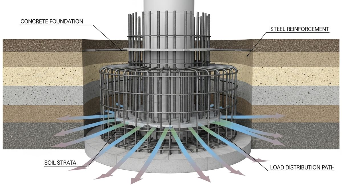
Wind Turbine Foundations Explained: Structural Integrity and Design
In my two decades of experience managing large-scale infrastructure projects, I have learned that the foundation is the most critical, yet often overlooked, component of a wind turbine. While the blades and nacelle capture the headlines, the foundation must withstand extreme cyclic loading, overturning moments, and environmental stressors for over 25 years.
Designing these structures requires a deep understanding of soil mechanics, concrete fatigue, and dynamic load analysis. Whether we are dealing with soft coastal clays or dense rock, the foundation must prevent excessive tilting and settlement that could lead to catastrophic structural failure. This guide breaks down the technical requirements and methodologies I use to ensure project longevity.
Key Takeaways for Engineers:
Wind Turbine Foundations Design and Structural Mechanics
Wind Turbine Foundations Design: The systematic application of structural and geotechnical engineering principles to mitigate overturning moments and cyclic fatigue, ensuring compliance with IEC 61400-1 design load requirements.
When I approach the design of a wind turbine foundation, I start by calculating the extreme overturning moment. The turbine tower acts as a massive lever arm; the wind force at the hub height creates a moment that the foundation must resist through its self-weight and the soil’s bearing capacity. The primary design equation involves checking the eccentricity of the resultant force, which must remain within the middle third of the foundation base to prevent uplift.
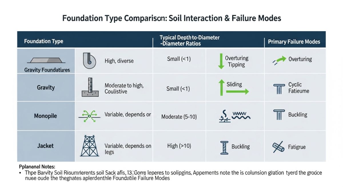
Dynamic Load and Fatigue Analysis
Unlike static structures, wind turbines experience constant vibration. I calculate the natural frequency of the foundation-tower system to avoid resonance with the rotor frequency (1P) and the blade passing frequency (3P). If the foundation stiffness is too low, the system enters a resonance state, leading to rapid fatigue of the anchor bolts and concrete cracking.
Field Warning: The Anchor Bolt Cage
The anchor bolt assembly is the most common point of failure. In my experience, improper tensioning or poor grout consolidation leads to micro-movements. Always specify high-strength, pre-stressed bolts and verify the grout’s compressive strength against the tower base plate requirements.
Geotechnical Parameters and Soil Interaction
The soil-structure interaction model is vital. I utilize the p-y curve method to model the lateral resistance of the soil. For gravity foundations, the bearing pressure must be checked against the allowable soil bearing capacity under both serviceability limit states (SLS) and ultimate limit states (ULS). If the soil is too soft, I pivot to pile-supported foundations, which transfer the load to deeper, more competent strata.
For pile foundations, the design must account for negative skin friction and lateral pile capacity. I typically use a group of piles connected by a reinforced concrete pile cap. The pile-to-cap connection is a critical detail; it must be designed to transfer the full moment without rotation. I always insist on performing a static load test on a sacrificial pile before finalizing the design for the entire wind farm.
Foundation Selection Trade-offs: The technical evaluation of structural efficiency, cost-effectiveness, and site-specific geotechnical constraints when choosing between gravity, pile, or hybrid foundation systems.
Advantages
- Gravity bases offer rapid construction in high-bearing-capacity soils.
- Pile foundations provide superior stability in soft, compressible, or liquefiable soils.
- Hybrid systems optimize material usage by combining deep piles with shallow gravity caps.
- Standardized designs allow for modular pre-casting, reducing site labor costs.
- High structural redundancy in pile groups ensures long-term safety.
Disadvantages
- Gravity foundations require massive concrete volumes, increasing carbon footprint.
- Pile installation involves heavy machinery and high mobilization costs.
- Complex soil-structure interaction requires expensive, multi-stage geotechnical testing.
- Anchor bolt fatigue remains a high-risk maintenance issue over 25 years.
- Offshore foundations face extreme corrosion risks, necessitating advanced cathodic protection.
Infrastructure Deployment Scenarios: The practical implementation of specialized foundation designs across diverse environmental and geological landscapes to support utility-scale wind energy generation.
Onshore Utility-Scale Wind Farms
In flat, inland plains with stable soil, gravity foundations are the industry standard. These designs utilize the weight of the concrete base to counteract the overturning moment, providing a cost-effective solution that minimizes the need for deep excavation or piling.
Coastal and Marshland Developments
When building in coastal regions with high water tables or soft alluvial deposits, pile foundations are essential. By driving steel or concrete piles into deeper, load-bearing strata, we bypass the unstable surface layers, ensuring the turbine remains perfectly vertical despite soil settlement.
Offshore Fixed-Bottom Installations
Offshore environments require monopile or jacket foundations designed for extreme wave and current loading. These structures incorporate specialized transition pieces and scour protection systems to prevent seabed erosion around the base, maintaining structural integrity in harsh marine conditions.
Selecting the appropriate foundation type for a wind turbine requires a rigorous evaluation of soil mechanics, structural loading, and environmental constraints. The following table outlines the primary design parameters that dictate the transition from a standard gravity base to complex pile-supported offshore structures. These values represent typical ranges encountered during the preliminary design phase, though site-specific geotechnical reports remain the final authority for structural sizing.
Engineers must balance the overturning moment, which is the most critical load case for tall wind towers, against the bearing capacity of the soil. When soil conditions are poor, such as in soft clays or loose sands, the design must shift toward deep foundation systems to mitigate settlement and ensure long-term stability under cyclic loading. Always refer to ASCE and DNV-ST-0126 standards when finalizing these parameters for your specific project site.
| Foundation Type | Soil Suitability | Primary Load Mechanism | Standard Reference |
|---|---|---|---|
| Gravity Base | High Bearing Capacity | Mass/Overturning Resistance | ACI 318 |
| Monopile | Soft to Medium Soil | Lateral Soil Resistance | DNV-ST-0126 |
| Suction Caisson | Saturated Clay/Silt | Hydrostatic/Friction | ISO 19901 |
The data above highlights the necessity of matching the foundation’s mechanical behavior to the site’s geological profile. Failure to account for cyclic degradation in soil stiffness can lead to premature structural fatigue, particularly in offshore environments where wave-induced loading compounds the turbine’s operational vibrations.
This matrix provides a structured overview of the technical entities and regulatory frameworks governing wind turbine foundation design. By mapping physical parameters to their respective engineering standards, we ensure that every design phase—from initial geotechnical investigation to final structural verification—remains compliant with global safety requirements.
The integration of these entities is critical for project lifecycle management. For instance, the interaction between the turbine’s natural frequency and the foundation’s stiffness must be analyzed to avoid resonance, which is a common failure mode in high-capacity wind energy projects. Use this matrix as a reference guide during the design review process to verify that all structural components are accounted for in your load calculations.
| Entity/Parameter | Acronym | Standard/Code |
|---|---|---|
| Ultimate Limit State | ULS | IEC 61400-1 |
| Serviceability Limit State | SLS | Eurocode 3 |
| Soil-Structure Interaction | SSI | API RP 2GEO |
Maintaining strict adherence to these standards is not merely a regulatory requirement but a fundamental engineering practice to ensure the longevity of renewable infrastructure. Always document the specific version of the code used in your design calculations to facilitate future audits and maintenance planning.
Foundation Design Verification: Before finalizing the structural design of any wind turbine foundation, it is imperative to conduct a comprehensive site verification. This process ensures that the theoretical model aligns with the physical realities of the project site, minimizing the risk of differential settlement or structural failure during the turbine’s operational lifespan.
-
[ ]
Geotechnical Data Validation: Verify that the borehole logs cover the entire depth of the foundation influence zone, including potential liquefaction layers. -
[ ]
Groundwater Table Assessment: Confirm the seasonal high-water mark to account for buoyancy effects and potential pore-water pressure buildup in the soil. -
[ ]
Cyclic Loading Analysis: Ensure the foundation design accounts for the long-term fatigue effects of wind-induced vibrations on the soil-structure interface. -
[ ]
Corrosion Protection Audit: Validate that cathodic protection systems or concrete cover thicknesses meet ISO 12944 requirements for the specific environment. -
[ ]
Load Path Continuity: Check that the transition piece connection to the foundation is designed to transfer extreme bending moments without localized stress concentrations.
Following this checklist provides a systematic approach to risk mitigation. In my experience, the most frequent site issues arise from neglecting the interaction between the foundation and the surrounding soil under extreme weather events. Always perform a sensitivity analysis on your soil parameters to understand how variations in soil stiffness impact the overall structural stability of the turbine tower.
Problem: Unexpected Differential Settlement in Coastal Wind Farm
- Initial geotechnical reports failed to identify a thin, highly compressible organic silt layer beneath the primary bearing stratum.
- The turbine experienced a tilt exceeding the operational limit of 0.5 degrees within the first six months of commissioning.
- Cyclic loading from the turbine exacerbated the settlement, leading to micro-cracking in the reinforced concrete base.
- The project faced significant downtime due to the need for emergency structural monitoring and potential foundation remediation.
Outcome: Successful Remediation via Micropiling
- Engineers implemented a series of high-capacity micropiles to bypass the compressible layer and transfer loads to the deeper, stable bedrock.
- The foundation was successfully leveled using hydraulic jacking techniques, restoring the turbine to its design verticality.
- Post-remediation monitoring showed zero additional settlement over a 24-month observation period.
- The project team updated the site investigation protocol to require deeper, more frequent borehole sampling for all future phases.
This case study underscores the importance of thorough site characterization. Even a minor oversight in the geotechnical investigation can lead to major structural challenges. I recommend always performing a secondary review of soil data by an independent third party to ensure that no critical layers are missed during the initial assessment phase.
Frequently Asked Engineering Questions
How do I determine the natural frequency of a foundation?
- Model the foundation as a rigid or flexible body depending on the soil stiffness.
- Use finite element analysis to calculate the system’s stiffness matrix and mass matrix.
- Ensure the natural frequency avoids the 1P (rotor frequency) and 3P (blade passing frequency) ranges to prevent resonance.
- Refer to IEC 61400-1 for specific guidance on frequency avoidance criteria.
What is the role of the transition piece in offshore foundations?
- It provides a level platform for the tower installation, compensating for any verticality deviations in the pile.
- It houses secondary components such as boat landings, cable entry systems, and internal platforms.
- The connection, often a grouted joint or bolted flange, must be designed to withstand extreme fatigue loads.
- Compliance with DNV-ST-0126 is essential for the structural integrity of this connection.
Why is cyclic loading a major concern for foundations?
- In saturated soils, cyclic loads can increase pore-water pressure, potentially leading to liquefaction.
- The accumulation of plastic strain in the soil can cause the foundation to tilt or settle unevenly.
- Designers must use cyclic p-y curves to model the soil response accurately under these conditions.
- Standard practice involves performing a fatigue analysis based on the expected load cycles over a 20-25 year design life.
How do I select between gravity and pile foundations?
- Gravity foundations are preferred for sites with high bearing capacity and shallow bedrock.
- Pile foundations are necessary for soft, deep soil profiles where gravity bases would be too large or prone to settlement.
- Environmental factors, such as water depth and scour potential, also influence the choice.
- A cost-benefit analysis should compare the material volume of gravity bases against the installation complexity of deep pile systems.
What are the primary scour protection requirements?
- Common methods include rock dumping or the use of concrete mattresses to armor the seabed.
- The design must account for the hydrodynamic forces of currents and waves that drive sediment transport.
- Regular inspections are required to ensure the protection layer remains intact throughout the project life.
- Refer to API RP 2GEO for guidelines on calculating scour depth and protection sizing.
How is the design life of a foundation verified?
- Calculate the cumulative damage using the Palmgren-Miner rule for all expected load cycles.
- Ensure that the corrosion allowance for steel components is sufficient for the entire service period.
- Perform periodic structural health monitoring to detect any deviations from the design model.
- All verification steps must be documented in accordance with IEC 61400-1 to ensure project certification.
Complete Course on
Piping Engineering
Check Now
Key Features
- 125+ Hours Content
- 500+ Recorded Lectures
- 20+ Years Exp.
- Lifetime Access
Coverage
- Codes & Standards
- Layouts & Design
- Material Eng.
- Stress Analysis
