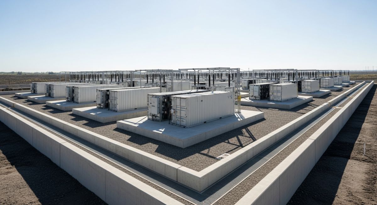
Flood Protection for BESS Facilities: Engineering Design Strategies
In my two decades of experience designing industrial energy infrastructure, I have observed that the most overlooked risk to Battery Energy Storage Systems (BESS) is not fire, but water. As we push for rapid deployment of grid-scale storage, we often place these assets in flood-prone zones without adequate hydraulic modeling. A single flood event can lead to catastrophic short-circuiting, electrolyte leakage, and total asset loss.
This guide focuses on the civil and structural engineering requirements for protecting BESS assets. We will examine how to calculate the Flood Protection Level (FPL), design robust bunding, and integrate stormwater management systems that keep your facility operational during extreme weather events.
Key Takeaways for BESS Flood Resilience:
- Establish the FPL based on 500-year flood event data rather than 100-year minimums.
- Prioritize vertical elevation of battery containers over perimeter barriers alone.
- Ensure all secondary containment systems are hydrostatically tested for water-tightness.
- Integrate redundant, gravity-fed drainage paths to prevent ponding around electrical cabinets.
Flood Protection for BESS Facilities: Technical Design Analysis
Flood Protection for BESS Facilities: The systematic application of civil engineering principles to elevate, isolate, and drain critical energy storage infrastructure against hydrostatic and hydrodynamic flood loads.
Designing for flood resilience requires a multi-layered approach. We start with the Flood Protection Level (FPL), which I define as the Base Flood Elevation (BFE) plus a minimum freeboard of 600mm to 1000mm, depending on the site’s criticality. For BESS, we must account for the specific sensitivity of the Battery Management System (BMS) and the potential for thermal runaway if water contacts the battery cells.
Hydrostatic Load Calculations
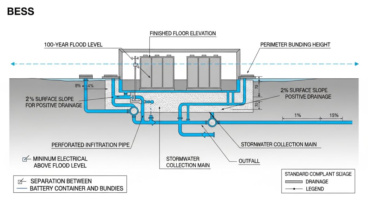
When designing perimeter flood walls or bunds, we must calculate the hydrostatic pressure exerted by standing water. The pressure at any depth is calculated as P = rho * g * h, where rho is the density of water, g is gravity, and h is the depth of the water. For a 1-meter flood depth, the pressure at the base of the wall is approximately 9.81 kN/m2.
Engineering Warning: Buoyancy Forces
Do not ignore buoyancy. If a BESS container is empty or partially filled, the upward force (Archimedes’ principle) can exceed the downward force of the container’s dead weight. You must anchor containers to the concrete plinth using high-strength, corrosion-resistant bolts capable of resisting the uplift force calculated as F_buoyancy = V_submerged * rho_water * g.
Foundation Elevation and Drainage
Elevating the BESS containers on reinforced concrete plinths is the most effective mitigation strategy. I recommend a minimum plinth height of 500mm above the finished grade. This creates a physical barrier against sheet flow and minor ponding. Furthermore, the site grading must be designed with a minimum slope of 1% away from the containers toward designated stormwater swales or detention basins.
For sites with high water tables, we must incorporate sub-surface drainage (French drains) to prevent saturation of the subgrade, which could lead to differential settlement of the heavy battery containers. All electrical conduits entering the containers must be sealed with water-tight glands to prevent water migration through the cable trenches, which are often the weakest point in a flood protection design.
Flood Mitigation Trade-offs: A comparative analysis of structural elevation versus perimeter containment strategies for BESS site resilience.
Advantages of Elevated Foundations
- Eliminates the need for complex, active flood-gate systems.
- Provides natural ventilation beneath the containers, reducing cooling loads.
- Simplifies cable routing and maintenance access for technicians.
- Offers superior protection against both sheet flow and standing water.
- Reduces the reliance on perimeter wall structural integrity.
Disadvantages of Perimeter Barriers
- Requires constant maintenance of seals and gate mechanisms.
- Creates a “bathtub effect” if internal drainage fails during heavy rain.
- Significant footprint requirements for large-scale flood walls.
- High risk of failure if hydrostatic pressure exceeds design limits.
- Potential for debris accumulation blocking drainage outlets.
BESS Deployment Scenarios: Tailored flood protection strategies for diverse industrial and utility-scale energy storage environments.
Coastal Utility-Scale Storage
In coastal regions, BESS facilities face the dual threat of storm surges and high water tables. We utilize elevated concrete platforms combined with salt-spray resistant coatings to ensure that both flood and corrosive environmental factors are mitigated simultaneously.
Floodplain Industrial Microgrids
For facilities located within 100-year floodplains, we implement a “dry floodproofing” strategy. This involves sealing all penetrations and using perimeter berms to divert water flow, ensuring the BESS remains operational even when the surrounding site is inundated.
Urban Brownfield Redevelopment
Urban sites often have limited space for large drainage swales. We utilize modular, high-capacity underground detention tanks beneath the BESS array to manage stormwater runoff, effectively turning the foundation footprint into a dual-purpose flood management system.
Designing robust flood protection for Battery Energy Storage Systems (BESS) requires a precise alignment between hydrological data and structural resilience. In my experience, the selection of design parameters is not merely a compliance exercise but a fundamental risk mitigation strategy to prevent catastrophic thermal runaway triggered by water ingress. The following table outlines the critical design thresholds I typically enforce during the front-end engineering design (FEED) phase to ensure that electrical enclosures and battery racks remain isolated from floodwaters.
These parameters are derived from ASCE 24 standards for flood-resistant design and construction. When evaluating these metrics, engineers must account for the specific site topography and the potential for localized ponding, which often exceeds regional flood map predictions. Always prioritize the highest recorded flood elevation plus a mandatory freeboard allowance to account for climate-induced variability in storm intensity.
| Parameter | Standard/Reference | Design Threshold |
|---|---|---|
| Design Flood Elevation (DFE) | FEMA BFE + Freeboard | BFE + 1.0m (Minimum) |
| Enclosure Ingress Protection | IEC 60529 | IP65 or Higher |
| Bunding Capacity | Local Environmental Code | 110% of Total Electrolyte Volume |
| Structural Load (Hydrostatic) | ASCE 7 | Calculated for DFE Depth |
The complexity of BESS infrastructure necessitates a multi-disciplinary approach where civil, electrical, and environmental engineering intersect. This matrix serves as a technical roadmap for project managers and lead engineers to identify the specific standards and physical parameters that govern flood protection for BESS facilities. By mapping these entities, we ensure that no critical component—from the battery management system (BMS) sensors to the perimeter drainage—is overlooked during the design review process.
In my professional practice, I utilize this matrix to cross-reference regulatory requirements with site-specific physical constraints. It is essential to recognize that while electrical standards focus on internal safety, civil standards dictate the external environment. Integrating these two domains is the only way to achieve a truly resilient installation that can withstand extreme weather events without compromising the integrity of the energy storage assets.
Verifying the flood resilience of a BESS site requires a systematic audit of both the physical infrastructure and the operational procedures. During my site inspections, I rely on a rigorous checklist to ensure that the design intent matches the field reality. This process is not just about checking boxes; it is about identifying potential failure points where water could bypass protective measures, such as cable trenches, conduit entries, or ventilation louvers.
-
01.
Confirm site finished floor elevation (FFE) is at least 300mm above the 100-year flood level. -
02.
Verify all cable trenches are sealed with water-tight, fire-rated penetration seals per NFPA 855. -
03.
Inspect perimeter bunding for structural cracks and ensure drainage valves are in the closed position. -
04.
Check that all outdoor electrical enclosures meet the specified IP65 rating for water ingress protection. -
05.
Validate that emergency shutdown systems (ESD) are elevated or protected against submersion. -
06.
Confirm that stormwater management systems are clear of debris and sized for the 50-year storm event.
Each item on this list must be documented with photographic evidence and signed off by the lead civil engineer. If any item fails verification, the site must be considered at risk, and temporary mitigation measures—such as sandbagging or portable pumping systems—must be deployed immediately until permanent repairs are completed. Remember, the goal is to maintain the integrity of the battery modules under all foreseeable hydrological conditions.
The Challenge: Inadequate Drainage at a Coastal BESS Facility
A 50MW BESS facility experienced significant water ingress during a high-intensity storm event due to a failure in the site’s primary drainage design.
- Underestimation of peak runoff coefficients for the site’s paved areas.
- Clogged drainage grates caused by wind-blown debris during the storm.
- Cable trenches acting as conduits for water to enter the battery containers.
- Lack of secondary containment for potential electrolyte leaks during flooding.
The Outcome: Successful Remediation and System Hardening
Following the incident, the site underwent a comprehensive redesign to ensure future resilience against extreme weather events.
- Installation of a raised concrete plinth system for all battery containers.
- Implementation of a redundant, automated pumping system with backup power.
- Sealing of all underground cable entries with high-density, water-resistant compounds.
- Redesign of the site grading to direct runoff away from critical electrical infrastructure.
My recommendation for similar projects is to always perform a sensitivity analysis on your drainage calculations. Do not rely solely on historical data; incorporate a safety factor that accounts for the increasing frequency of extreme precipitation events. A proactive investment in site grading and sealing is significantly cheaper than the cost of replacing damaged battery modules or dealing with the environmental cleanup of a flooded site.
How do I determine the appropriate freeboard for BESS sites?
- Consult ASCE 24 for specific regional guidance on freeboard requirements.
- Consider the potential for wave action if the site is near a large body of water.
- Account for climate change projections that suggest higher peak flood levels over the next 20 years.
What are the primary risks of water ingress in BESS?
- Corrosion of electrical contacts and busbars, leading to long-term reliability issues.
- Potential for electrolyte leakage if the battery casing is compromised by water pressure.
- Failure of the Battery Management System (BMS) sensors, which can lead to incorrect state-of-charge reporting.
How does bunding protect the environment during a flood?
- It ensures that any leaked chemicals are contained within the site footprint.
- Bunding prevents the cross-contamination of floodwaters with toxic battery components.
- It provides a controlled area for emergency response teams to neutralize and clean up spills.
Are there specific standards for BESS flood protection?
How can I improve drainage in existing BESS facilities?
- Install permeable paving to reduce the overall runoff coefficient of the site.
- Add redundant pumping systems that are triggered by water level sensors.
- Ensure that all existing drainage channels are regularly cleared of debris and vegetation.
What role does the BMS play during a flood?
- The BMS can isolate individual battery racks to prevent a localized fault from spreading.
- It provides real-time data to operators, allowing for informed decision-making during an emergency.
- Integration with site-wide flood sensors can allow the BMS to initiate a proactive shutdown before water reaches the equipment.
Complete Course on
Piping Engineering
Check Now
Key Features
- 125+ Hours Content
- 500+ Recorded Lectures
- 20+ Years Exp.
- Lifetime Access
Coverage
- Codes & Standards
- Layouts & Design
- Material Eng.
- Stress Analysis
