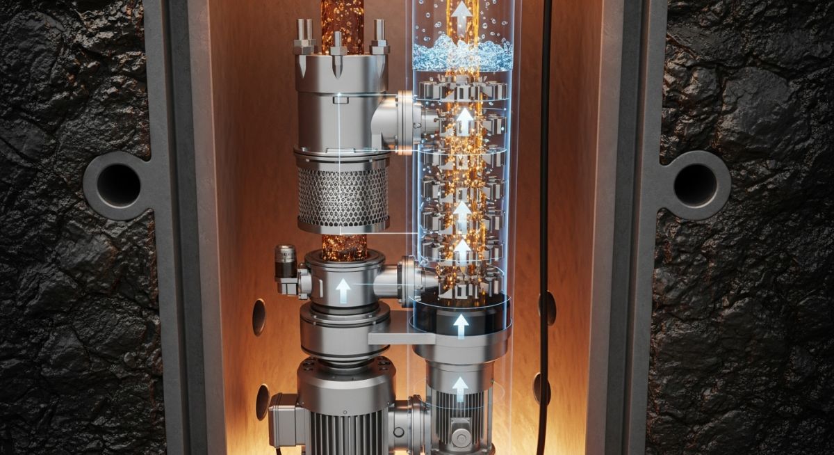
Electrical Submersible Pumps: Working Principle, Components, and Industrial Applications
In my 20-plus years of commissioning downhole systems, I have seen many engineers underestimate the sheer complexity of electrical submersible pumps. These are not your standard surface-mounted centrifugal units; they operate in some of the most hostile environments on earth, thousands of feet below the surface under extreme pressures and temperatures. When an ESP fails, the downtime costs can easily spiral into hundreds of thousands of dollars per day, which is why understanding their mechanical limits and electrical parameters is non-negotiable.
Key Engineering Takeaways
- Mastering downhole motor cooling dynamics prevents premature winding insulation failure.
- Correct sizing of the protector (seal section) is the single most critical factor for motor longevity.
- Variable speed drives (VSDs) must be tuned to avoid mechanical resonance frequencies.
- Cable selection must account for decompression rates to prevent gas decompression damage.
- Strict adherence to API RP 11S4 during installation reduces infant mortality rates of downhole assemblies.
How Electrical Submersible Pumps Optimize Artificial Lift
An ESP operates as a multistage centrifugal pump. Each stage consists of a rotating impeller and a stationary diffuser. As fluid enters the impeller, it is accelerated radially outward, gaining kinetic energy. The fluid then enters the diffuser, where its velocity is reduced, converting that kinetic energy into pressure energy. This pressure increase is cumulative across all stages, allowing the pump to generate the massive head required to lift fluids from deep reservoirs.
Total Dynamic Head (TDH) Calculations
To size an ESP correctly, we must calculate the Total Dynamic Head (TDH). The formula is expressed as:
Where:
HD = Vertical lift (depth to fluid level under dynamic pumping conditions, in feet)
HF = Friction loss in the production tubing (in feet)
HP = Tubing discharge pressure (wellhead pressure converted to feet of fluid)
Let us walk through a real-world project scenario. Suppose we have a dynamic fluid level (HD) of 6,000 feet. The friction loss (HF) at a target flow rate of 1,500 barrels per day (BPD) through 2-7/8 inch tubing is calculated at 15 feet per 1,000 feet of tubing, yielding HF = 90 feet. The wellhead pressure is 150 psi, and the fluid specific gravity (SG) is 0.85.
First, convert the wellhead pressure to feet of head:
Now, calculate the TDH:
Motor Horsepower Sizing
Once the TDH is established, we determine the required motor horsepower (HP_motor) using the following formula:
Assuming a pump efficiency of 68% (0.68) at the Best Efficiency Point (BEP):
HP_motor = (1,500 * 6,497.6 * 0.85) / (135,770 * 0.68) = 8,284,440 / 92,323.6 = 89.7 HP.
In practice, I would select a 100 HP motor to provide a safety margin of at least 10%, ensuring the motor does not run at its thermal limit.
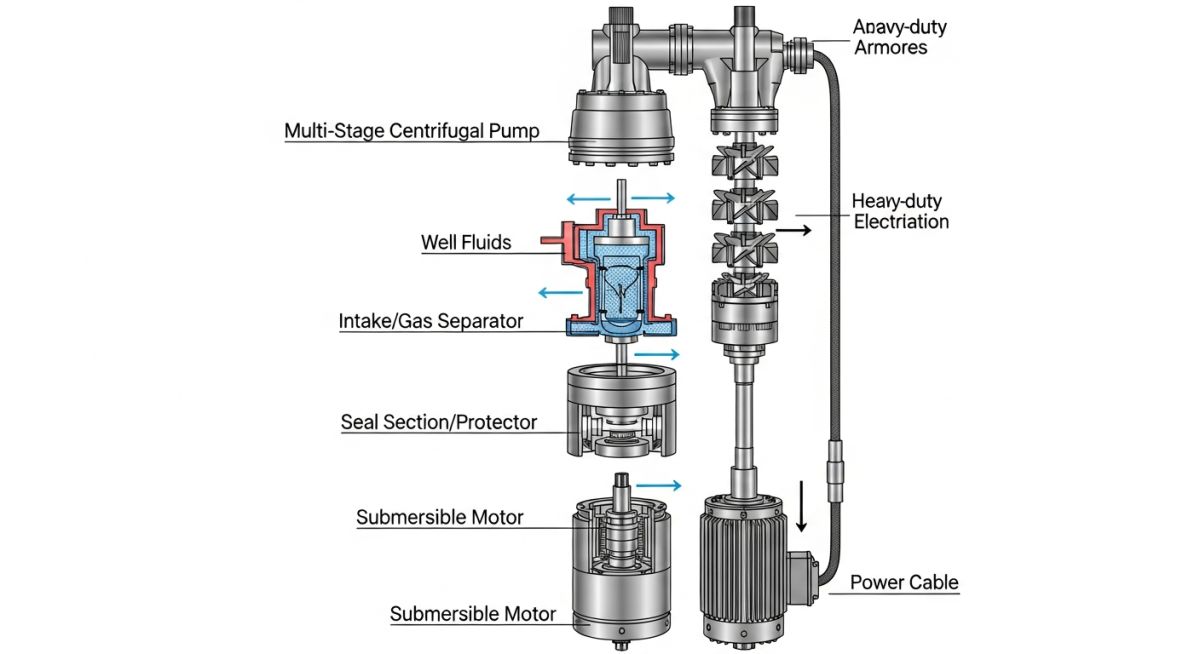
| Component | Primary Function | Key Design Parameters | API Standard Reference |
|---|---|---|---|
| Multistage Pump | Generates head to lift fluid | Impeller diameter, Stage count, Best Efficiency Point (BEP) | API RP 11S3 |
| Submersible Motor | Drives the pump shaft | Voltage, Amperage, Heat dissipation, Insulation Class H | API RP 11S4 |
| Protector / Seal | Equalizes pressure & prevents fluid ingress | Mechanical seal type, Elastomer rating, Thrust bearing capacity | API RP 11S1 |
| Gas Separator | Separates free gas from liquid | Gas volume fraction (GVF), Vortex vs. static design | API RP 11S2 |
| Power Cable | Delivers surface power downhole | Conductor size, Armor type (EPDM/Lead), Voltage drop | API RP 11S5 |
| Parameter | Metric Unit | Imperial Unit | Critical Threshold / Engineering Rule |
|---|---|---|---|
| Minimum Fluid Velocity | 0.3 m/s | 1.0 ft/s | Minimum required past motor for adequate cooling. |
| Maximum Gas Volume Fraction (GVF) | 10% (Standard) | 10% (Standard) | Higher GVF requires rotary gas separators or gas mitigators. |
| Motor Insulation Class | Class H (180°C) | Class H (356°F) | Maximum continuous operating temperature limit. |
| Cable Voltage Drop | < 5% | < 5% | Minimize resistive heating and maintain motor terminal voltage. |
| Vibration Limit | 1.5 mm/s RMS | 0.06 in/s RMS | High vibration indicates shaft misalignment or gas locking. |
Installing Electrical Submersible Pumps Safely
Before lowering the assembly into the wellbore, every interface must be verified. In my experience, over 40% of early-life failures are directly traceable to handling damage or improper torque during make-up on the rig floor.
Field Verification Checkpoints
-
[ ]
Insulation Resistance (Megger) Test: Perform a 1000V DC megger test on the motor and cable assembly before run-in-hole (RIH). Minimum acceptable reading is 1000 Megohms. -
[ ]
Shaft Rotation Check: Manually rotate the pump, protector, and motor shafts to ensure free movement without binding or catching. -
[ ]
Protector Oil Filling: Fill the protector with high-dielectric barrier oil, ensuring all air bubbles are completely purged. -
[ ]
Cable Guard Installation: Install heavy-duty cross-coupling cable guards at every tubing joint to prevent pinching against the casing. -
[ ]
Splice Integrity: Verify that the downhole cable-to-motor lead (MLE) splice is vulcanized or taped to withstand dynamic wellbore pressures. -
[ ]
Torque Verification: Use calibrated torque wrenches to make up all housing connections to manufacturer-specified limits. -
[ ]
Surface Controller Check: Verify that the Variable Speed Drive (VSD) overcurrent and underload trip settings match the motor nameplate data.
Field Case Study: Real-World Application
Direct Recommendation: Always calculate the actual fluid velocity in the casing-to-motor annulus. If it falls below 1.0 ft/s, a cooling shroud is mandatory, regardless of reservoir temperature.
Frequently Asked Engineering Questions
What causes gas locking in electrical submersible pumps?
How does a variable speed drive (VSD) benefit ESP operations?
What is the purpose of the protector (seal section) in an ESP?
How do you select the correct power cable for downhole deployment?
What are the primary indicators of ESP wear or impending failure?
How does fluid viscosity affect ESP performance?
Complete Course on
Piping Engineering
Check Now
Key Features
- 125+ Hours Content
- 500+ Recorded Lectures
- 20+ Years Exp.
- Lifetime Access
Coverage
- Codes & Standards
- Layouts & Design
- Material Eng.
- Stress Analysis