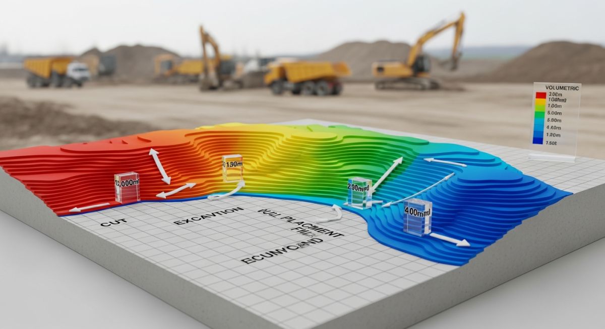
Mastering Cut and Fill Quantities for Civil Site Development
In my two decades of experience managing large-scale industrial and civil projects, I have learned that the most significant cost overruns often hide beneath the surface. Mastering cut and fill quantities is not merely a mathematical exercise; it is the backbone of site feasibility and project profitability. When we talk about earthworks, we are balancing the removal of high-elevation soil (cut) with the placement of material in low-lying areas (fill) to create a stable, level platform for infrastructure.
Effective earthwork management requires a deep understanding of soil mechanics, compaction factors, and site topography. If you fail to account for the swell and shrinkage of soil types, your project will inevitably face budget deficits due to unexpected material procurement or disposal fees. This guide breaks down the technical rigor required to master these volumes.
Key Takeaways
- Accurate volume estimation prevents costly material import/export cycles.
- Understanding soil shrinkage and swell factors is critical for mass balance.
- Proper site grading ensures long-term structural integrity and drainage.
- Environmental compliance hinges on minimizing site disturbance and erosion.
Technical Analysis of Cut and Fill Quantities
Earthwork Volumetric Analysis: The application of geometric principles and geotechnical data to determine the precise volume of soil movement required to meet design grade elevations per ASCE standards.
To calculate earthwork volumes, we primarily utilize the Average End Area method. This method assumes that the volume between two cross-sections is the average of their areas multiplied by the distance between them. The formula is expressed as V = (A1 + A2) / 2 * L, where V is the volume, A1 and A2 are the cross-sectional areas at two stations, and L is the horizontal distance between them.
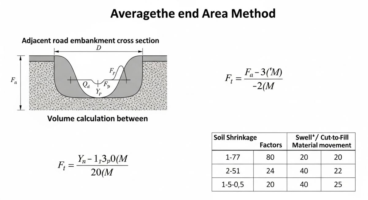
However, raw volume calculations are rarely sufficient for real-world site conditions. We must apply a shrinkage factor (for fill) and a swell factor (for cut) to account for the change in soil density. When soil is excavated, it occupies more volume than it did in its natural, compacted state (swell). Conversely, when placed as fill, it is compacted to a specific density, reducing its volume (shrinkage).
Field Warning: Soil Compaction Discrepancies
Failure to apply the correct Proctor density test results to your volume calculations will lead to significant mass balance errors. Always verify the soil classification (e.g., AASHTO M 145) before finalizing your cut and fill quantities.
In my experience, the most robust approach involves creating a digital terrain model (DTM) that compares existing ground levels with proposed design grades. By calculating the difference at every grid point, we generate a precise cut-fill map. This allows us to identify “borrow pits” or “spoil areas” early in the design phase, significantly reducing the project’s carbon footprint and logistics costs.
When dealing with deep excavations, we must also consider the angle of repose and the necessity of shoring or benching. These factors increase the total volume of cut required beyond the theoretical design footprint. Always reference OSHA standards for trenching and excavation safety when planning these operations.
Earthwork Strategic Assessment: A comparative evaluation of the operational, financial, and environmental trade-offs inherent in balancing site earthworks for large-scale infrastructure projects.
Advantages
- Cost Optimization: Balancing cut and fill on-site eliminates expensive soil hauling and disposal fees.
- Resource Efficiency: Reusing native soil reduces the need for importing expensive structural fill materials.
- Schedule Acceleration: On-site balancing minimizes the logistics of managing external material supply chains.
- Environmental Stewardship: Reducing truck traffic lowers the project’s overall carbon emissions and site disturbance.
Disadvantages
- Geotechnical Risk: Unsuitable native soil may require chemical stabilization or replacement, increasing costs.
- Weather Sensitivity: High moisture content in excavated soil can halt compaction operations during rainy seasons.
- Complex Logistics: Managing large-scale earthmoving equipment requires significant site space and traffic control.
- Regulatory Hurdles: Strict environmental permits are often required for large-scale grading and soil stockpiling.
Industrial Earthwork Implementation: The practical application of cut and fill methodologies across diverse sectors to ensure structural stability and operational efficiency.
Industrial Plant Site Grading
Large-scale industrial facilities require perfectly level pads for heavy equipment foundations. By calculating precise cut and fill quantities, engineers ensure that the site can support massive static and dynamic loads without differential settlement.
Highway and Rail Embankments
Linear infrastructure projects rely on continuous mass balance to create stable roadbeds. We use cut material from high-elevation sections to construct embankments in low-lying areas, maintaining a consistent grade for safe transit.
Stormwater Management Basins
Creating retention ponds involves significant excavation to manage site runoff. The excavated material is often repurposed as structural fill for parking lots or building pads, demonstrating a circular approach to site development.
Landfill Cell Construction
Engineers design landfill cells to maximize capacity while ensuring environmental containment. Precise cut and fill management is essential for creating the required slopes for leachate collection and long-term structural stability.
Accurate estimation of earthwork volumes requires a rigorous application of geometric principles to site survey data. In my experience, the choice of calculation method—whether Average End Area, Prismoidal, or Grid-based—directly influences the precision of your project budget and equipment scheduling. These methods are governed by ASCE guidelines and local civil engineering standards, which dictate how we handle cross-sectional transitions and terrain irregularities.
The table below outlines the primary methodologies used in modern site grading. Selecting the correct approach depends on the complexity of the terrain and the density of your survey points. For instance, while the Average End Area method is standard for linear infrastructure, it often overestimates volumes in highly curved or undulating landscapes, necessitating the more complex Prismoidal formula to maintain accuracy within acceptable tolerances.
| Methodology | Best Application | Accuracy Level | Code Reference |
|---|---|---|---|
| Average End Area | Linear Roadways/Rail | Moderate | ASTM D698 |
| Prismoidal Formula | Complex Curvature | High | AASHTO M145 |
| Grid/TIN Method | Site Grading/Pads | Very High | ISO 19157 |
Always remember that these calculations represent theoretical volumes. You must apply a shrinkage or swell factor based on the specific soil classification—such as clay, sand, or rock—to determine the actual “bank” versus “loose” volume required for your fleet logistics.
Managing earthwork data requires a structured approach to mapping physical site parameters to engineering specifications. This matrix serves as a reference for project managers and site engineers to ensure that all soil movement activities align with geotechnical reports and environmental compliance mandates. By standardizing these entities, we reduce the risk of miscommunication between the design office and the field operations team.
The following matrix correlates critical engineering entities with their respective industry standards and physical properties. This mapping is essential for maintaining consistency in BIM (Building Information Modeling) workflows and ensuring that the digital twin of the site accurately reflects the physical reality of the cut and fill operations being performed on the ground.
| Entity | Acronym | Standard | Key Parameter |
|---|---|---|---|
| Soil Compaction | MDD | ASTM D1557 | Dry Density |
| Swell Factor | SF | AASHTO T99 | Volume Ratio |
| Bearing Capacity | CBR | ASTM D1883 | Load Resistance |
Utilizing these standardized parameters ensures that your earthwork strategy remains defensible during audits and inspections. Always verify that your site-specific geotechnical report references these exact standards to avoid discrepancies in material performance expectations.
Effective earthwork management is not merely about moving dirt; it is about precision, safety, and regulatory compliance. Before commencing any major excavation or embankment construction, I mandate a comprehensive site verification process. This checklist ensures that all variables—from soil moisture content to environmental erosion controls—are accounted for, minimizing the risk of costly rework or project delays.
Pre-Earthwork Verification Points
- ✓ Geotechnical Validation: Confirm that the soil classification matches the design assumptions per ASTM D2487.
- ✓ Erosion Control: Verify that silt fences and sediment basins are installed according to EPA SWPPP guidelines.
- ✓ Survey Control: Ensure site benchmarks are verified against local geodetic markers to prevent vertical elevation errors.
- ✓ Utility Clearance: Confirm all underground utilities are marked and verified via ground-penetrating radar or vacuum excavation.
- ✓ Moisture Testing: Perform field moisture-density tests to ensure compliance with the specified compaction requirements.
Following this checklist is non-negotiable for high-stakes infrastructure projects. In my experience, the most common cause of failure in earthworks is the neglect of moisture-density relationships during the fill placement phase. By validating these parameters daily, you maintain the structural integrity of the subgrade and ensure that the final project meets the long-term performance criteria defined in the initial design specifications.
The Problem: Unforeseen Soil Swell in Industrial Pad Construction
A major industrial facility project faced a 25% volume discrepancy between the design model and the actual excavated material, leading to significant budget overruns.
- Inaccurate initial geotechnical sampling failing to identify high-plasticity clay layers.
- Failure to account for the specific swell factor of the local soil under heavy rainfall.
- Inadequate stockpile management leading to moisture saturation of the fill material.
- Lack of real-time survey updates during the initial cut phase.
The Outcome: Optimized Earthwork Management and Cost Recovery
By implementing a revised earthwork management strategy, the project team successfully stabilized the site and recovered the schedule.
- Achieved a 15% reduction in material handling costs through on-site soil stabilization.
- Implemented a dynamic digital twin model that updated cut/fill volumes daily.
- Reduced environmental impact by reusing 90% of the excavated material on-site.
- Successfully met all compaction density requirements per ASTM D1557.
My recommendation for similar projects is to prioritize early-stage geotechnical density testing. Do not rely solely on regional averages; perform site-specific testing to determine the true swell and shrinkage factors. This proactive approach is the only way to ensure that your cut and fill quantities remain accurate throughout the lifecycle of the construction project.
Frequently Asked Engineering Questions
How do I calculate the shrinkage factor for clay soils?
- Conduct laboratory testing per ASTM D698 to establish the maximum dry density.
- Calculate the ratio of the bank density to the compacted density.
- Apply this factor to your total cut volume to estimate the required fill volume.
- Always account for moisture content, as clay soils are highly sensitive to water-induced volume changes.
What is the difference between bank and loose volume?
- Bank volume is the basis for most design estimates and earthwork calculations.
- Loose volume is critical for equipment sizing, as it determines the number of truckloads required.
- The conversion factor between these two states is known as the swell factor.
- Ignoring this distinction often leads to significant underestimation of transport costs and equipment requirements.
Why is the Prismoidal formula preferred for complex sites?
- It provides a more accurate volume for non-linear, irregular site grading.
- It is the standard for high-precision civil engineering projects where volume accuracy is critical.
- It reduces the “error of approximation” inherent in linear interpolation methods.
- Consult AASHTO standards for specific application guidelines regarding prismoidal corrections.
How do environmental regulations impact earthwork planning?
- Projects must adhere to EPA Stormwater Pollution Prevention Plans (SWPPP).
- Site grading must minimize runoff to prevent sediment discharge into local waterways.
- Disturbed areas must be stabilized immediately to prevent soil erosion.
- Failure to comply can result in significant fines and project shutdowns.
What role does BIM play in cut and fill?
- BIM allows for real-time volume calculations as the site topography changes.
- It facilitates better coordination between the design team and field operators.
- It enables the simulation of different grading scenarios to optimize cut and fill balance.
- It serves as a single source of truth for all project stakeholders.
How do I manage excess cut material on-site?
- Identify potential on-site uses such as landscaping berms or noise barriers.
- Evaluate the feasibility of soil stabilization to reuse material as structural fill.
- If off-site disposal is necessary, ensure compliance with local waste management regulations.
- Always prioritize on-site reuse to minimize transportation costs and carbon footprint.
Complete Course on
Piping Engineering
Check Now
Key Features
- 125+ Hours Content
- 500+ Recorded Lectures
- 20+ Years Exp.
- Lifetime Access
Coverage
- Codes & Standards
- Layouts & Design
- Material Eng.
- Stress Analysis
