Table of Contents
What is the Petroleum Refining Process and How Does It Work?
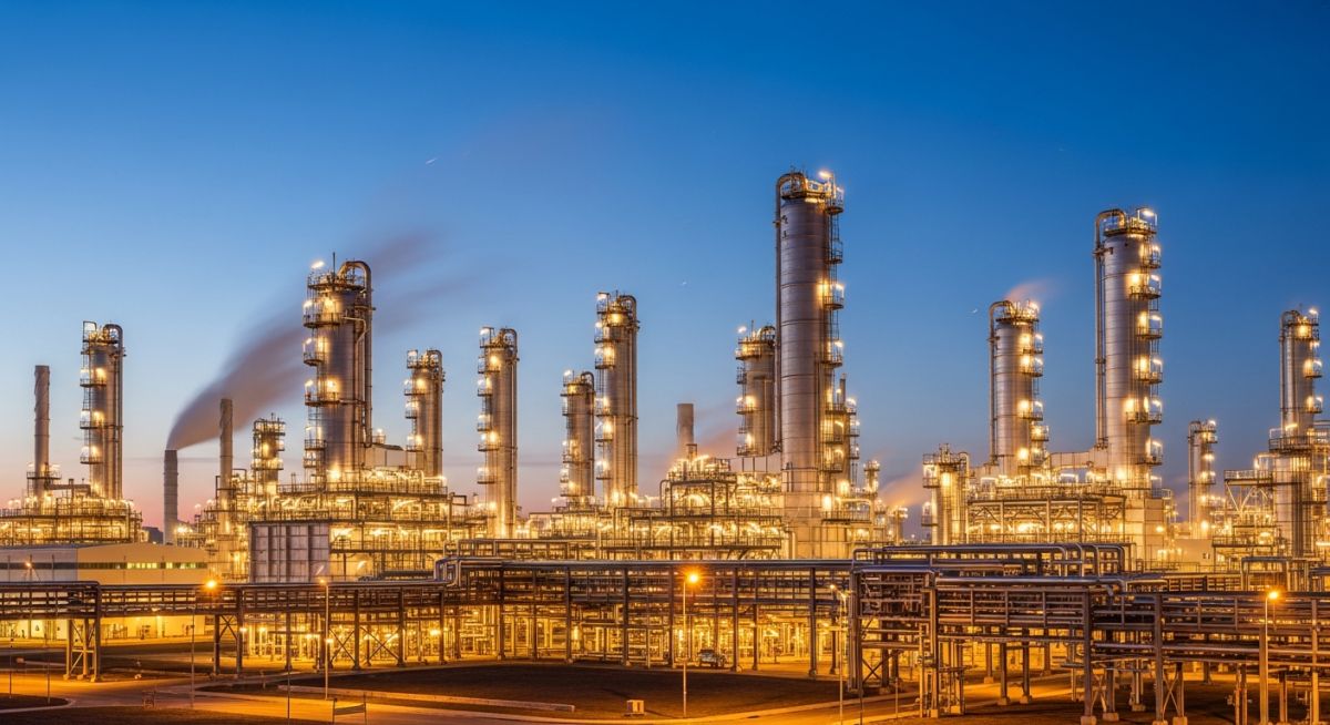
In my 20-plus years of commissioning refinery piping systems and troubleshooting distillation columns, I have walked the gravel paths of some of the largest petrochemical complexes in the world. The sheer scale of a modern refinery is breathtaking, but beneath the maze of steel pipes, valves, and roaring furnaces lies a beautifully logical, highly controlled thermodynamic sequence. Raw crude oil, as it comes out of the ground, is practically useless. It is a dark, viscous soup of thousands of different hydrocarbon molecules. The refining process is the master key that unlocks this raw resource, separating, cracking, and purifying those molecules into the precise fuels and chemical building blocks that power global industry.
When I consult on refinery design projects, I always emphasize that refining is not just about heating oil; it is about managing phase equilibrium, chemical kinetics, and mechanical integrity simultaneously. Every valve turn and temperature shift has a cascading effect downstream. If your atmospheric column experiences a minor pressure upset, your downstream hydrotreater or catalytic cracker will feel the shockwave within minutes. Understanding this interconnectedness is what separates a standard field engineer from a true refining specialist.
Key Engineering Takeaways
- Fractional Distillation: The foundational physical separation step based on boiling point differentials.
- Conversion Processes: Chemical alteration methods like cracking and reforming that reshape molecular structures.
- Metallurgical Integrity: Selecting the correct piping alloys to withstand high-temperature sulfidation and naphthenic acid corrosion.
- Environmental Compliance: Integrating hydrotreating and sulfur recovery units to meet stringent global emissions mandates.
Complete Course on
Piping Engineering
Check Now
Key Features
- 125+ Hours Content
- 500+ Recorded Lectures
- 20+ Years Exp.
- Lifetime Access
Coverage
- Codes & Standards
- Layouts & Design
- Material Eng.
- Stress Analysis
How Does the Petroleum Refining Process Separate Crude?
The journey of crude oil begins at the desalting unit, where water, inorganic salts, and suspended solids are washed out to prevent severe fouling and corrosion in downstream heat exchangers. Once desalted, the crude is preheated through a train of heat exchangers and then routed to the direct-fired crude furnace. Here, we blast the oil with heat, raising its temperature to approximately 340 degrees Celsius to 370 degrees Celsius (644 degrees Fahrenheit to 698 degrees Fahrenheit). At this temperature, a massive portion of the crude flashes into vapor.
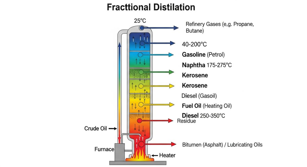
This partially vaporized stream enters the flash zone of the Atmospheric Distillation Column (CDU). The column itself is a towering vertical pressure vessel containing 30 to 50 fractionation trays. As the vapor rises through the trays, it cools. Hydrocarbons with higher boiling points condense near the bottom, while lighter, lower-boiling-point molecules rise to the top before condensing.
To calculate the maximum allowable vapor velocity inside the distillation column and prevent liquid entrainment (flooding), we rely on the classic Souders-Brown equation:
Where:
• Vmax = Maximum allowable vapor velocity (feet per second)
• C = Capacity factor (typically ranging from 0.15 to 0.35, depending on tray spacing and surface tension)
• rho_L = Liquid density at operating temperature (pounds per cubic foot)
• rho_V = Vapor density at operating temperature (pounds per cubic foot)
Transitioning to Vacuum Distillation
The heavy residue left at the bottom of the atmospheric column contains valuable heavy hydrocarbons that cannot be boiled off at atmospheric pressure without cracking them. To extract these, we route the atmospheric residue to the Vacuum Distillation Unit (VDU). By pulling a deep vacuum—typically 10 to 40 millimeters of mercury absolute (mmHg)—we lower the boiling points of these heavy molecules. This allows us to vaporize and recover Vacuum Gas Oils (VGO) at temperatures well below their thermal cracking threshold, preserving the molecular integrity of the feedstocks destined for the Fluid Catalytic Cracker (FCC).
Downstream Chemical Conversion
Separation is only the first phase. To match market demand, we must chemically alter these fractions. In the Fluid Catalytic Cracking unit, we take heavy VGO and contact it with a hot, fluidized zeolite catalyst at high temperatures. This breaks (cracks) the long-chain hydrocarbons into highly valuable, high-octane gasoline components and light olefins.
Conversely, in the Catalytic Reforming unit, we take low-octane heavy naphtha and pass it over a platinum-rhenium catalyst under high pressure. This process rearranges paraffinic and naphthenic molecules into aromatic rings, producing high-octane reformate for gasoline blending and generating massive quantities of hydrogen gas as a byproduct, which is recycled directly to our hydrotreating units.
Key Fractions in the Petroleum Refining Process
Managing a refinery requires precise knowledge of the physical properties of each cut. The table below outlines the typical boiling ranges, carbon numbers, and recommended piping materials for the primary fractions derived from the atmospheric and vacuum distillation columns.
| Fraction Name | Boiling Range (°C) | Carbon Range | Primary Downstream Unit | Piping Material Class |
|---|---|---|---|---|
| Light Naphtha | 30 to 90 | C5 to C6 | Isomerization Unit | Carbon Steel (A106-B) |
| Heavy Naphtha | 90 to 180 | C7 to C9 | Catalytic Reformer | Carbon Steel / Low Alloy |
| Kerosene / Jet Fuel | 180 to 250 | C10 to C13 | Merox / Hydrotreater | Carbon Steel |
| Light Gas Oil (Diesel) | 250 to 320 | C14 to C20 | Hydrodesulfurization | Carbon Steel / 5Cr-0.5Mo |
| Heavy Gas Oil | 320 to 370 | C20 to C25 | Fluid Catalytic Cracker | 5Cr-0.5Mo / 9Cr-1Mo |
| Vacuum Gas Oil (VGO) | 370 to 560 | C25 to C50 | Hydrocracker / FCC | 316L Stainless Steel |
To maintain mechanical integrity across the refinery, piping and vessel specifications must align with the operating envelopes of each unit. Below is the engineering mapping matrix for core refinery units.
| Process Unit | Core Equipment | Operating Pressure | Operating Temp | Primary Damage Mechanism | Design Code |
|---|---|---|---|---|---|
| Desalter | Electrostatic Vessel | 10 to 15 barg | 110 to 140 °C | Salt deposition, Wet H2S | ASME Sec VIII Div 1 |
| Atmospheric Distillation | Fractionation Column | 1.2 to 1.8 barg | 340 to 370 °C | Sulfidic Corrosion, Naphthenic Acid | API STD 510 |
| Hydrocracker | Fixed-Bed Reactor | 100 to 180 barg | 380 to 440 °C | High-Temp Hydrogen Attack (HTHA) | API RP 941 |
| Fluid Catalytic Cracking | Reactor & Regenerator | 1.5 to 3.0 barg | 500 to 730 °C | Erosion, Thermal Fatigue, Carburization | ASME B31.3 |
Refinery Piping Pre-Commissioning Verification Steps
Before introducing hydrocarbons into any newly constructed or modified refinery unit, a rigorous field verification must be executed. In my experience, skipping even a single check on a high-pressure hydrotreater circuit can lead to catastrophic leaks during startup. Use this checklist to verify system readiness.
Field Verification Checklist
-
Hydrostatic Test Verification: Ensure all piping loops have been hydrostatically tested to 1.5 times the design pressure in accordance with ASME B31.3, with test records signed off by the inspector.
-
Spring Hanger Cold-Setting: Verify that all variable and constant spring hangers are set to their designated “cold” positions and that travel stops have been removed prior to line heating.
-
Flange Alignment and Torque: Confirm that flange face alignment, parallelism, and bolt torque values meet the specifications of ASME PCC-1, especially on high-temperature exchanger nozzles.
-
Positive Material Identification (PMI): Double-check that all alloy piping components (such as 1-1/4Cr, 5Cr, or 316 SS) have undergone 100% PMI testing to prevent accidental carbon steel substitution in high-temperature sulfidation services.
-
Control Valve Bypass Alignment: Verify that all control valve bypass loops are fully isolated, with block valves closed and bleed valves open, to prevent uncontrolled process bypass during startup.
Field Case Study: Real-World Application
The Problem: Severe Flooding in a Vacuum Distillation Unit
During a major refinery expansion in East Asia, a newly commissioned Vacuum Distillation Unit (VDU) experienced severe pressure drop spikes and premature liquid flooding in the wash bed section. The unit was processing a heavy, high-TAN (Total Acid Number) crude oil. Within three weeks of startup, the vacuum gas oil (VGO) product quality degraded rapidly, showing high metal and carbon residue carryover. The field team suspected tray damage or severe packing fouling, but the root cause remained elusive without a deep hydraulic and metallurgical audit.
The Outcome: Redesign and Metallurgical Upgrade
I was called to the site to lead the investigation. We performed a gamma-scan of the column, which revealed massive liquid hold-up above the wash bed. Upon shutdown and inspection, we discovered that the liquid distributor was severely out of level (by more than 12 millimeters), causing massive liquid maldistribution. Furthermore, the 410 Stainless Steel structured packing had suffered severe naphthenic acid corrosion, which thinned the metal sheets and caused them to collapse under the liquid load.
We executed a two-fold solution: we replaced the collapsed packing with high-performance structured packing fabricated from 317L Stainless Steel (containing 3% to 4% molybdenum to resist naphthenic acid attack). We also redesigned the gravity distributor, installing a state-of-the-art deck with a leveling tolerance of +/- 1.5 millimeters. Upon restarting the unit, the column pressure drop fell by 45%, and VGO recovery increased by 3.2%, yielding an estimated annual savings of 4.2 million USD.
This case highlights the critical importance of matching metallurgy to the specific chemical profile of the crude feed. When processing high-TAN crudes, standard stainless steels will fail rapidly under high-temperature vacuum conditions. Always consult API RP 939-C for guidelines on avoiding sulfidation and naphthenic acid corrosion.
Frequently Asked Engineering Questions
What is the difference between atmospheric and vacuum distillation?
Why is desalting crude oil necessary before refining?
How does hydrotreating differ from hydrocracking?
What are the primary damage mechanisms in a crude utility unit?
What is the role of catalytic reforming in gasoline production?
How does the refinery manage sour gas and sulfur recovery?

📚 Recommended Resources: petroleum refining process
Read these Guides
🎓 Advanced Training


Related posts:
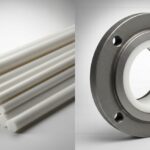
![Comparison of raw PTFE material and an industrial PTFE-lined steel pipe flange]()
Teflon vs PTFE: Major Differences in Industrial Piping Applications
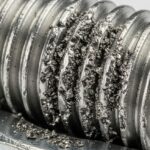
![Severe metal galling damage on a stainless steel threaded bolt and nut.]()
What is Metal Galling and How to Prevent It
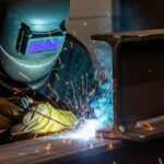
![Certified welder performing structural welding repair on a heavy steel beam with sparks flying.]()
Mastering Industrial Welding Repair Procedures for Structural Integrity
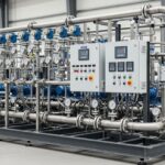
![A fully assembled industrial pump skid system with stainless steel piping and control panels in a factory.]()
What is an Industrial Pump Skid and Its Key Advantages?
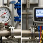
![Side-by-side comparison of an industrial flow meter and a digital flow transmitter installed on a pipeline.]()
Flow Transmitter vs Flow Meter: Key Differences Explained
![Wireless vibration sensor mounted on an industrial electric motor for condition monitoring.]()
What is Vibration Monitoring and Why is it Important?