Concentric vs Eccentric Pipe Reducers: Engineering Design and Selection Guide
In my 20 years of managing refinery piping layouts and troubleshooting fluid flow anomalies, I have seen minor design oversights lead to catastrophic pump failures. One of the most common yet misunderstood decisions a piping designer faces is selecting and orienting the correct pipe reducer. Whether you are dealing with high-velocity steam lines or volatile hydrocarbon pump suctions, choosing between a concentric and an eccentric reducer is not just a matter of space—it is a fundamental decision that dictates fluid dynamics, structural loading, and system longevity.
Throughout my career, I have audited dozens of piping and instrumentation diagrams (P&IDs) where concentric reducers were incorrectly specified for horizontal pump suctions, leading to severe vapor pocketing and subsequent impeller cavitation. In this comprehensive guide, I will share the practical field realities, mathematical design parameters, and code compliance steps necessary to make the right engineering choice every single time.
Key Engineering Takeaways
- Understand the geometric differences that govern flow transition and centerline alignment.
- Master the rules of horizontal pump suction orientation to prevent cavitation.
- Learn how to maintain bottom-of-pipe (BOP) elevations in pipe racks using eccentric reducers.
- Apply ASME B31.3 wall thickness and stress intensification factor (SIF) calculations.
Why Choose Concentric vs Eccentric Pipe Reducers?
Reducer Selection Criteria: The engineering decision-making process governing the choice between concentric and eccentric configurations to prevent vapor pocketing in pump suctions and maintain centerline alignment in pipe racks.
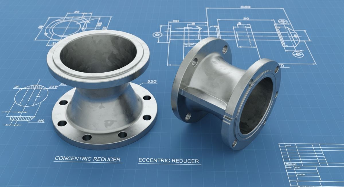
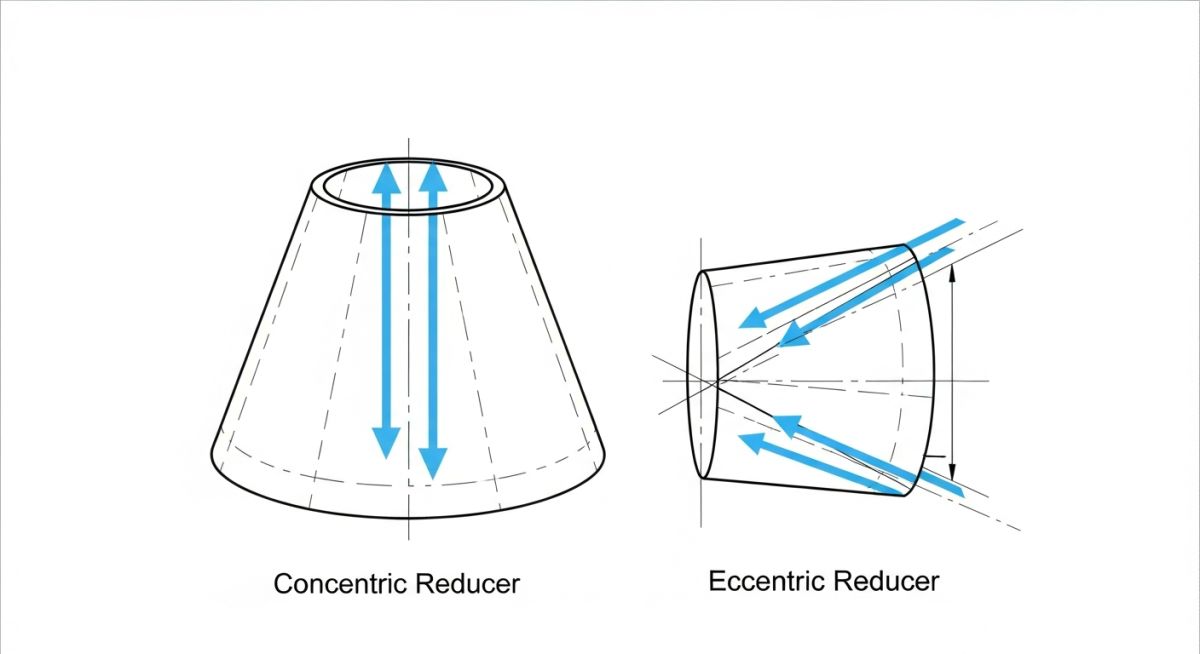
To understand why we use one over the other, we must first look at their geometry. A concentric reducer is symmetrical; the centerlines of both the larger and smaller pipes align perfectly. This creates a uniform, cone-shaped transition that minimizes turbulence and pressure drop. I always specify concentric reducers for vertical piping runs because they distribute fluid forces symmetrically and do not introduce eccentric structural loads.
An eccentric reducer, on the other hand, has offset centerlines. One side of the reducer is completely flat, while the other side slopes. This offset introduces a physical shift in the flow path. We use eccentric reducers primarily in horizontal piping runs. Depending on the process requirements, they are installed either “Flat-on-Top” (FOT) or “Flat-on-Bottom” (FOB).
Installing an eccentric reducer with the flat side down (FOB) on a horizontal pump suction line handling volatile liquids is a recipe for disaster. Vapor bubbles will accumulate at the top high point of the reducer, forming a pocket. When this pocket eventually breaks free, it enters the pump impeller as a large vapor slug, causing severe cavitation, vibration, and mechanical seal failure. Always specify Flat-on-Top (FOT) for horizontal pump suctions.
Design Calculations for Concentric vs Eccentric Pipe Reducers
Reducer Stress Analysis: Analytical evaluation of stress intensification factors and pressure drops across reducer geometries under ASME B31.3 piping flexibility requirements.
When designing a piping system under ASME B31.3, we must calculate the minimum required wall thickness of the reducer to withstand internal design pressure. Because a reducer is a transition component, its wall thickness must satisfy the requirements of both the large and small ends, taking into account the transition angle.
The design pressure thickness for the straight section of the pipe is calculated using the standard ASME B31.3 formula:
Where:
– t = Pressure design thickness of the pipe reducer (inches or mm).
– P = Internal design gage pressure (psi or MPa).
– D = Outside diameter of the pipe at the point under consideration.
– S = Allowable stress value for the material at design temperature per ASME B31.3 Table A-1.
– E = Quality factor of the longitudinal weld joint.
– W = Weld joint strength reduction factor.
– Y = Dimensionless coefficient from Table 304.1.1.
For reducers manufactured to ASME B16.9, the manufacturer guarantees that the pressure rating of the fitting is equal to or greater than that of straight pipe of the same material, schedule, and thickness. However, as a piping stress engineer, I must calculate the Stress Intensification Factor (SIF) at the reducer welds during flexibility analysis.
The SIF (denoted as i) for a concentric or eccentric reducer is calculated based on the transition angle (alpha) and the wall thickness. For standard reducers, the SIF is typically lower than that of a standard tee but higher than a straight run of pipe. If the transition angle exceeds 60 degrees, the SIF increases rapidly, which is why standard ASME B16.9 reducers maintain a gentle transition angle (usually between 15 and 30 degrees).
Let us look at the pressure drop calculation. The head loss (h_f) across a reducer can be estimated using the resistance coefficient method:
Where K is the resistance coefficient, v is the fluid velocity at the smaller end, and g is the acceleration due to gravity. For a gradual concentric reducer, the K-factor is extremely low (often between 0.05 and 0.15), whereas an eccentric reducer introduces a slightly higher K-factor due to the asymmetric flow profile and localized turbulence along the sloped wall.
The table below outlines the standard dimensions for butt-welding concentric and eccentric reducers in accordance with ASME B16.9. Note that the face-to-face length (H) remains identical for both concentric and eccentric configurations of the same nominal size.
| Nominal Pipe Size (NPS) | Large End OD (inches) | Small End OD (inches) | Length H (inches) | Approx. Weight (lbs – Sch 40) |
|---|---|---|---|---|
| 2 x 1 | 2.375 | 1.315 | 3.00 | 1.6 |
| 3 x 2 | 3.500 | 2.375 | 3.50 | 3.2 |
| 4 x 3 | 4.500 | 3.500 | 4.00 | 5.5 |
| 6 x 4 | 6.625 | 4.500 | 5.50 | 11.2 |
| 8 x 6 | 8.625 | 6.625 | 6.00 | 19.5 |
This matrix maps the core technical entities, structural configurations, and fluid dynamics impacts of concentric and eccentric reducers to assist in rapid design selection.
| Reducer Type | Geometric Profile | Primary Application | Fluid Dynamics Impact | ASME Code Reference |
|---|---|---|---|---|
| Concentric Reducer | Symmetrical cone, shared centerline | Vertical lines, gas/steam lines, control valve manifolds | Uniform velocity profile, minimal turbulence, lowest pressure drop | ASME B16.9 / ASME B31.3 |
| Eccentric Reducer (FOT) | Flat on top, offset centerline | Horizontal pump suction (liquid service) | Prevents vapor pocketing, ensures smooth liquid flow into pump | ASME B16.9 / API RP 686 |
| Eccentric Reducer (FOB) | Flat on bottom, offset centerline | Horizontal pipe racks, slurry lines | Maintains common bottom-of-pipe elevation, prevents solids accumulation | ASME B16.9 / ASME B31.3 |
How to Verify Reducer Installation Quality?
Quality Verification Protocol: Field inspection procedures designed to confirm correct orientation, alignment tolerances, and material compliance of piping reducers prior to hydrotesting.
During my site audits, I always carry a checklist to verify that the construction team has installed the reducers exactly as specified in the isometric drawings. A single reversed eccentric reducer can shut down an entire process unit due to pump damage. Use this field-verified checklist during your next walkdown.
Field Verification Checklist
-
Orientation Check (Pump Suction): Verify that horizontal pump suction lines utilize eccentric reducers installed Flat-on-Top (FOT) to prevent vapor pocketing.
-
Orientation Check (Pipe Racks): Confirm that horizontal pipe rack runs utilize eccentric reducers installed Flat-on-Bottom (FOB) to maintain a uniform bottom-of-pipe (BOP) elevation for support steel.
-
Material Grade Verification: Cross-reference the material stamping on the reducer body (e.g., ASTM A234 WPB, WP304L) with the piping specification and mill test reports (MTRs).
-
Fit-Up and Alignment: Check the weld fit-up gap and internal alignment (high-low) per ASME B31.3 requirements to minimize stress concentration at the weld joints.
-
Drainage and Venting: Ensure that vertical concentric reducers do not create liquid traps in systems that require complete self-draining capabilities.
Field Case Study: Real-World Application
The Problem: Chronic Cavitation in a Hydrocarbon Transfer Pump
At a major petrochemical facility in Texas, a newly commissioned centrifugal hydrocarbon transfer pump experienced severe vibration (exceeding 12 mm/s RMS) and seal leaks within 48 hours of startup. The operations team suspected a faulty pump impeller or shaft misalignment. Upon reviewing the physical piping layout, I noticed that the horizontal suction line transitioned from an 8-inch header to a 6-inch pump nozzle using an eccentric reducer installed Flat-on-Bottom (FOB). Because the fluid was a volatile light hydrocarbon, vapor bubbles were collecting at the top of the reducer, forming a massive gas pocket that periodically collapsed into the pump.
The Outcome: Corrective Engineering and Vibration Reduction
I issued an immediate field modification order to cut out the FOB eccentric reducer and replace it with a new eccentric reducer oriented Flat-on-Top (FOT) in accordance with API RP 686. Once the system was restarted, the vapor pocketing was completely eliminated. The pump’s vibration levels dropped immediately to a stable 1.8 mm/s RMS, and the mechanical seals have operated without a single leak for over three years. This simple geometric correction saved the refinery an estimated 120,000 in recurring maintenance costs and lost production.
My direct recommendation to all piping designers is to double-check the isometric drawings against the P&ID notes before releasing them to the fabrication shop. Never assume the field crew knows the correct orientation of an eccentric reducer unless it is explicitly marked on the drawing.
Frequently Asked Engineering Questions
What is the primary difference between concentric and eccentric reducers?
Why is an eccentric reducer installed flat-on-top in pump suction lines?
When should an eccentric reducer be installed flat-on-bottom?
How do you calculate the length of a standard pipe reducer?
What are the stress intensification factors for reducers under ASME B31.3?
Can concentric reducers be used in vertical piping runs?
Complete Course on
Piping Engineering
Check Now
Key Features
- 125+ Hours Content
- 500+ Recorded Lectures
- 20+ Years Exp.
- Lifetime Access
Coverage
- Codes & Standards
- Layouts & Design
- Material Eng.
- Stress Analysis



