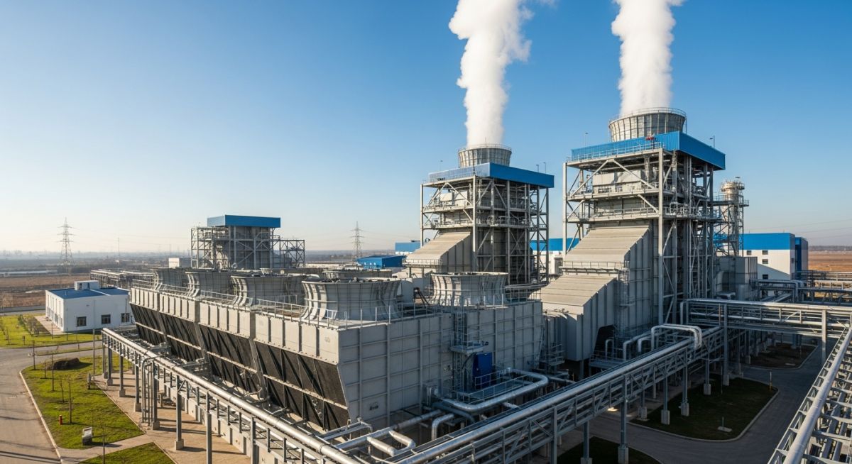
Design and Engineering of Mechanical Draft Cooling Towers
In my 20 years of piping and process plant design, I have seen many engineers treat cooling towers as simple utility boxes. They are not. A poorly specified mechanical draft cooling tower can bottleneck an entire petrochemical facility or power plant. I remember a project in the Middle East where a minor miscalculation in the wet-bulb design temperature led to a 15 percent drop in steam turbine efficiency during peak summer. This guide draws on my field experience to break down the design, thermal calculations, and structural realities of these workhorses.
- Understand the thermodynamic differences between induced draft and forced draft configurations.
- Master the application of Merkel’s Equation for heat transfer calculations without relying on black-box software.
- Identify structural and piping stress limitations at the tower interface.
- Implement robust field verification protocols to guarantee performance compliance.
How Do Mechanical Draft Cooling Towers Operate?
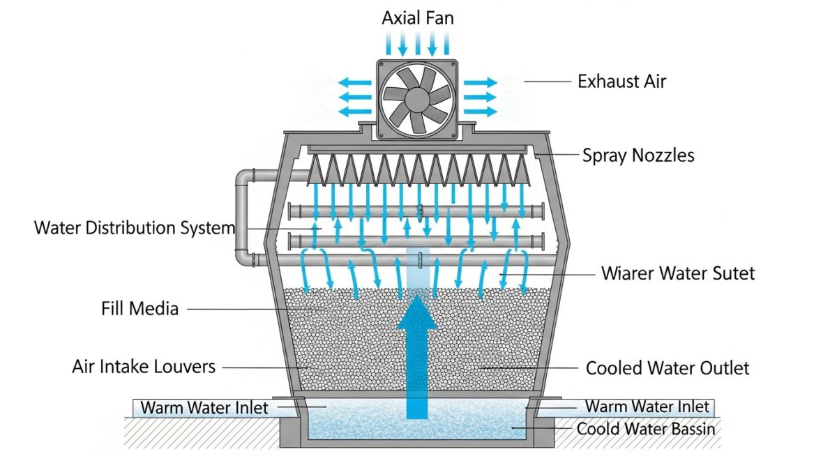
Mechanical draft towers are categorized into two primary configurations: induced draft and forced draft. In an induced draft tower, the fan is positioned at the top of the discharge stack, pulling air upward through the fill. In contrast, forced draft towers position the fan at the air inlet base, pushing air into the structure.
From a piping perspective, induced draft towers offer superior air distribution and minimize the risk of recirculation. Recirculation occurs when the warm, humid exhaust air is drawn back into the air inlets, severely degrading the thermal driving force. Because the discharge velocity in an induced draft tower is three to four times higher than the inlet velocity, the plume is projected far away from the intake louvers.
In my projects, I avoid forced draft towers in tight spaces or high-wind areas. Because the discharge velocity is low, wind can easily push the humid exhaust plume back down into the intake. This can raise the entering wet-bulb temperature by 3 to 5 degrees Fahrenheit, destroying your approach design.
The Mathematics of Heat Transfer: Merkel’s Equation
To size or evaluate these systems, we rely on the Merkel Equation, which integrates the sensible and latent heat transfer. The basic equation is expressed as:
Where:
- K = Mass transfer coefficient (pounds of water per hour per square foot of contact area).
- a = Contact area per unit volume of fill (square feet per cubic foot).
- V = Active cooling volume (cubic feet per square foot of plan area).
- L = Water mass flow rate (pounds per hour per square foot).
- t1, t2 = Entering and leaving water temperatures (degrees Fahrenheit).
- hw = Enthalpy of air-water vapor mixture at bulk water temperature (BTU per pound of dry air).
- ha = Enthalpy of air-water vapor mixture at local wet-bulb temperature (BTU per pound of dry air).
The term KaV/L is a dimensionless measure of the thermal capability of the tower. When designing piping systems for these towers, the water-to-air ratio (L/G) must be carefully balanced. If the water flow rate (L) is too high relative to the air flow rate (G), the tower will flood, causing a massive drop in thermal efficiency and high pressure drops across the drift eliminators.
For comprehensive testing and design standards, engineers must refer to the Cooling Technology Institute (CTI) standards and ASME PTC 23. These documents outline the exact procedures for measuring wet-bulb temperatures, water flow rates, and fan power consumption to verify performance guarantees.
Performance Metrics of Mechanical Draft Systems
The table below compares the operational characteristics of induced draft and forced draft configurations based on typical industrial project data.
| Parameter | Induced Draft (Counterflow) | Induced Draft (Crossflow) | Forced Draft |
|---|---|---|---|
| Air Velocity Profile | Highly uniform through fill | Uniform, horizontal flow | Non-uniform, high velocity at entry |
| Recirculation Tendency | Very Low (0.5% – 1.5%) | Low (1.0% – 2.0%) | High (5.0% – 10.0%) |
| Fan Location & Maintenance | Top-mounted; requires crane access | Top-mounted; easy plenum access | Ground-level; very easy access |
| Typical Approach Limits | 5°F to 7°F (2.8°C to 3.9°C) | 7°F to 10°F (3.9°C to 5.6°C) | 8°F to 12°F (4.4°C to 6.7°C) |
| Static Pressure Drop | Moderate (0.35 – 0.50 in. H2O) | Low (0.20 – 0.30 in. H2O) | High (0.50 – 0.75 in. H2O) |
Technical Mapping & Specifications Matrix
This matrix maps the core technical entities, structural acronyms, and physical parameters to their governing industry standards.
| Entity / Acronym | Technical Definition | Governing Standard | Design Impact |
|---|---|---|---|
| CTI STD-201 | Thermal Performance Certification Standard | CTI | Eliminates the need for field prototype testing. |
| L/G Ratio | Liquid-to-Gas mass flow ratio | ASME PTC 23 | Determines the slope of the operating line on the psychrometric chart. |
| Drift Loss | Entrained water droplets in exhaust air | EPA AP-42 | Typically limited to less than 0.005% of circulating water flow. |
| FRP Structure | Fiberglass Reinforced Polyester structural members | CTI ESG-152 | Provides corrosion resistance in highly acidic or saline water environments. |
How to Verify Mechanical Draft Cooling Towers?
Before you sign off on a newly installed mechanical draft cooling tower, you must perform a rigorous field verification. In my experience, skipping these checks can lead to catastrophic mechanical failures or immediate thermal performance shortfalls during the first hot season.
-
Fan Blade Pitch Angle: Verify that all fan blades are pitched within 0.5 degrees of each other using a digital protractor. Uneven pitch causes severe aerodynamic imbalance and vibration.
-
Fill Pack Alignment: Inspect the PVC or wood fill packs. Ensure there are no gaps between the fill and the tower casing. Gaps allow air to bypass the heat-transfer media entirely.
-
Nozzle Spray Pattern: Run the auxiliary pumps to check the distribution basin or spray nozzles. Look for clogged nozzles or dry spots on the fill. Uniform water distribution is critical.
-
Vibration Cut-out Switch: Test the mechanical vibration limit switch on the gear reducer support beam. It must trip the motor if vibration levels exceed 5 mils (0.127 mm) displacement.
-
Drift Eliminator Sealing: Ensure drift eliminators are tightly fitted with no gaps. Any gap will allow untreated water droplets to escape, violating local environmental particulate emissions standards.
Field Case Study: Real-World Application
During a summer expansion project, a Gulf Coast chemical plant reported that their 4-cell induced draft cooling tower could not maintain the design cold-water temperature of 85°F (29.4°C) when the wet-bulb temperature hit 78°F (25.6°C). The actual cold-water temperature was hovering around 89.5°F (31.9°C). This 4.5°F shortfall forced a production cutback on the downstream reactors.
I was called in to audit the system. Our initial measurements showed that the fan motors were drawing only 75% of their rated nameplate amperage, and the air discharge velocity was lower than specified.
We conducted a comprehensive thermal audit per CTI ATC-105. We discovered two major issues:
- The fan blades had been improperly pitched during a previous maintenance turnaround, set at 12 degrees instead of the design 16.5 degrees. This reduced the air mass flow rate (G) by nearly 22%.
- Severe biological fouling had clogged approximately 15% of the splash-fill nozzles, causing water channeling and reducing the effective contact area (a).
We shut down the cells sequentially, re-pitched the fan blades to 16.5 degrees, and replaced the clogged nozzles with non-clogging target nozzles.
The results were immediate. The fan motor amp draw returned to 94% of nameplate rating, air flow increased to design levels, and the cold-water temperature dropped to 84.7°F (29.3°C)—slightly exceeding the original design guarantee. This restored full production capacity to the reactors, saving the plant an estimated 120,000 per day in lost revenue.
My recommendation for any plant operator facing similar issues is to establish a semi-annual thermal audit program. Never rely solely on the control room readings; physically verify the fan pitch, motor amp draws, and nozzle spray patterns before the high-demand summer months arrive.
Frequently Asked Engineering Questions
What is the difference between “Range” and “Approach” in cooling tower design?
Why is the wet-bulb temperature more critical than the dry-bulb temperature?
How do you prevent biological fouling in the fill of mechanical draft towers?
What are the structural advantages of FRP over wood or concrete towers?
How does fan tip speed affect noise levels in mechanical draft towers?
What is plume abatement and how is it achieved mechanically?
Complete Course on
Piping Engineering
Check Now
Key Features
- 125+ Hours Content
- 500+ Recorded Lectures
- 20+ Years Exp.
- Lifetime Access
Coverage
- Codes & Standards
- Layouts & Design
- Material Eng.
- Stress Analysis