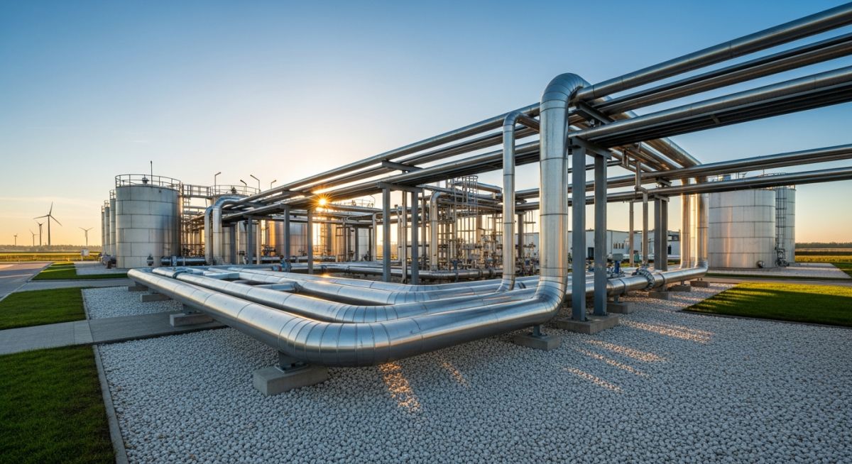
Introduction to Clean Energy Piping & Pipeline Systems Design
In my 20 years of piping engineering, I have watched our industry transition from traditional hydrocarbon networks to the complex, unforgiving world of clean energy piping systems. Designing for hydrogen or supercritical carbon dioxide is not simply a matter of copying and pasting your old ASME B31.3 templates. These molecules behave entirely differently under pressure. Hydrogen is tiny, highly diffusive, and actively attacks the crystalline structure of standard carbon steels. Carbon dioxide, when dry, is relatively benign, but a single drop of moisture turns it into a highly corrosive carbonic acid bath, while rapid decompression can freeze your valves solid. In this guide, I will share the hard-won field lessons and rigorous design calculations required to build safe, reliable green infrastructure.
Key Engineering Takeaways
- Understand the critical differences between ASME B31.12 and ASME B31.3/B31.4.
- Master the material selection criteria to prevent hydrogen embrittlement and rapid gas decompression.
- Calculate wall thicknesses using the hydrogen material performance factor.
- Implement robust field testing and commissioning protocols for clean energy networks.
Designing Clean Energy Piping Systems for Hydrogen Service
When we design piping for gaseous hydrogen, our primary adversary is Hydrogen Embrittlement (HE). Atomic hydrogen diffuses into the metal lattice, settling at grain boundaries and dislocations. This reduces the material’s ductility and fracture toughness, leading to sub-critical crack growth under static tensile stress. To combat this, ASME B31.12 provides two distinct design paths: Option A (Prescriptive Design) and Option B (Performance-Based Design).
Under Option A, we apply a material performance factor, designated as F, to reduce the allowable stress of the material. This factor accounts for the degrading effect of hydrogen on the steel’s mechanical properties. Let us look at the modified wall thickness equation for straight pipe under internal pressure:
Where:
t = Minimum design wall thickness (mm)
P = Internal design gauge pressure (MPa)
D = Outside diameter of the pipe (mm)
S = Basic allowable stress value for the material (MPa)
E = Joint quality factor
F = Hydrogen material performance factor (dimensionless, typically ranging from 0.50 to 1.00 depending on material grade and design pressure)
Y = Coefficient from ASME B31.3 (typically 0.4 for ductile metals at ambient temperatures)
Let us perform a practical calculation. Suppose we are designing a 12-inch NPS (323.9 mm outside diameter) pipeline for gaseous hydrogen service at a design pressure of 10 MPa. We are using seamless ASTM A106 Grade B carbon steel pipe. The basic allowable stress (S) at ambient temperature is 138 MPa, and the joint factor (E) is 1.0. According to ASME B31.12 Table IP-2.2.9-1, the hydrogen material performance factor (F) for this grade at 10 MPa is 0.85.
Denominator = 2 * 138 * 1.0 * 0.85 + 2 * 0.4 * 10
Denominator = 234.6 + 8.0 = 242.6 MPa
Numerator = P * D = 10 * 323.9 = 3239
t = 3239 / 242.6 = 13.35 mm
If we had ignored the hydrogen material performance factor and calculated this using standard ASME B31.3 rules (where F is effectively 1.0), the required thickness would be 11.40 mm. This difference of nearly 2 mm is the margin of safety required to prevent hydrogen-induced failure. In my experience, failing to apply this factor is one of the most common design errors made by engineers new to clean energy piping systems.
Material Selection for Clean Energy Piping Systems and CO2
Carbon dioxide transport presents a completely different set of engineering challenges. To transport CO2 efficiently over long distances, we must keep it in a supercritical or dense phase. This requires pressures above the critical point of 7.38 MPa and temperatures above 31.1 degrees Celsius. Typically, CO2 pipelines operate at pressures between 8.5 MPa and 15 MPa.
The primary hazard in supercritical CO2 systems is the presence of water. Pure, dry CO2 is non-corrosive to carbon steel. However, if free water is present, it reacts with the CO2 to form carbonic acid, which aggressively corrodes carbon steel at rates exceeding 10 mm per year. Therefore, we must strictly control the moisture limit, keeping it below 50 ppm, or transition to corrosion-resistant alloys (CRAs) such as duplex stainless steels (e.g., UNS S31803) in areas where water condensation is possible.
Another major concern is Rapid Gas Decompression (RGD) in non-metallic components. Supercritical CO2 easily diffuses into elastomeric seals. When the pipeline pressure drops rapidly during a shutdown or blowdown, the trapped CO2 expands violently within the elastomer, causing internal tearing, blistering, and seal failure. For clean energy piping systems handling CO2, we must specify RGD-resistant elastomers such as special grades of Hydrogenated Nitrile Butadiene Rubber (HNBR) or Fluorocarbon (FKM) that have been tested and certified under ISO 23936-2.
| Fluid Service | Phase / State | Recommended Metallurgy | Design Code | Key Damage Mechanism | Mitigation Strategy |
|---|---|---|---|---|---|
| Gaseous Hydrogen | High Pressure Gas | ASTM A312 Gr. 316L / API 5L X52 (with low hardness) | ASME B31.12 | Hydrogen Embrittlement (HE) | Limit hardness to 22 HRC; specify high nickel content (>12%) in stainless steels. |
| Liquid Hydrogen | Cryogenic Liquid (-253°C) | ASTM A312 Gr. 316/316L, 304/304L | ASME B31.12 | Low-Temperature Brittle Fracture | Use austenitic stainless steels; implement vacuum-jacketed piping insulation. |
| Carbon Dioxide | Supercritical / Dense Phase | API 5L X60 / X65 (with high Charpy toughness) | ASME B31.4 | Running Ductile Fracture; Carbonic Acid Corrosion | Maintain moisture < 50 ppm; specify high Charpy V-notch energy (>100 J) to arrest cracks. |
| Entity / Acronym | Technical Definition | Applicable Standard | Critical Engineering Parameter |
|---|---|---|---|
| ASME B31.12 | Standard for Hydrogen Piping and Pipelines | ASME B31.12 | Material performance factor (F) and design options A and B. |
| ISO 27913 | Carbon dioxide capture, transportation, and geological storage | ISO 27913 | Composition limits, fracture propagation control, and safety margins. |
| RGD | Rapid Gas Decompression in non-metallic seals | NORSOK M-710 / ISO 23936-2 | Seal hardness, extrusion resistance, and decompression rate limits. |
| CVN | Charpy V-Notch impact energy testing | ASTM E23 | Minimum energy absorption (Joules) at lowest design temperature. |
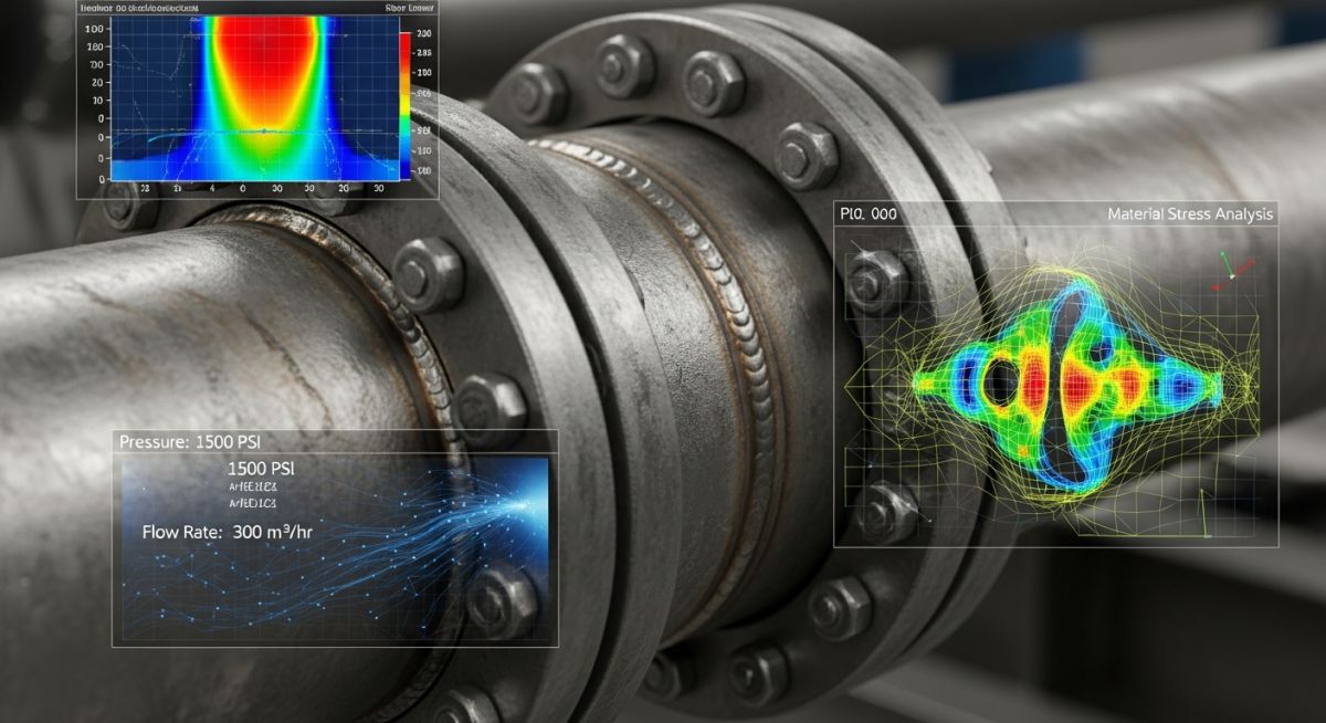
Before any clean energy piping system is energized, field engineers must execute a rigorous verification protocol. Because hydrogen is highly diffusive and CO2 is highly corrosive when wet, standard hydrostatic testing is often insufficient or must be followed by extreme drying procedures. Use this checklist on-site to ensure full compliance.
Pre-Commissioning Field Checklist
Cross-reference 100% of installed pipe heats with Mill Test Reports (MTRs). Confirm nickel content is above 12% for 316L stainless steel in hydrogen service.
Perform non-destructive hardness testing on 100% of welds and heat-affected zones (HAZ). Verify hardness remains below 22 HRC (237 HBW) to prevent hydrogen-induced cracking.
Conduct high-sensitivity helium leak testing on all mechanical joints, flanges, and valve packings. Hydrogen molecules will escape through paths that pass standard nitrogen bubble tests.
For CO2 pipelines, verify that the system has been dried to a dew point of less than -40°C (moisture content less than 5 ppm) before introducing CO2 to prevent carbonic acid formation.
Verify that all valve seals, gaskets, and O-rings are certified RGD-resistant (Rapid Gas Decompression) and compatible with supercritical CO2 or high-pressure hydrogen.
Field Case Study: Real-World Application
The Problem: Hydrogen-Induced Stress Cracking
A major green hydrogen blending facility in northern Europe experienced recurring micro-cracking at the heat-affected zones of several ASTM A106 Grade B piping joints. The system operated at 70 bar with a 20 percent hydrogen blend. Investigation revealed that the welding procedure did not specify post-weld heat treatment, resulting in localized hardness values exceeding 260 HV, which triggered hydrogen-induced stress cracking.
The Outcome: Hardness Control and Material Upgrade
I stepped in to overhaul the welding specification. We mandated 100 percent post-weld heat treatment for all carbon steel joints to reduce hardness below 200 HV (approximately 22 HRC). Additionally, we transitioned critical high-pressure blending manifolds to ASTM A312 Grade 316L stainless steel with a minimum nickel content of 12 percent. Subsequent helium leak testing and ultrasonic inspections confirmed zero defect propagation over 18 months of continuous operation.
My direct recommendation for any engineer designing clean energy piping systems is to never compromise on welding procedures. Hardness control is your primary defense against hydrogen embrittlement. Ensure your welding specifications are strictly aligned with ASME B31.12, and mandate field hardness testing as a non-negotiable quality control step.
Frequently Asked Engineering Questions
Why is ASME B31.12 preferred over ASME B31.3 for hydrogen piping?
What is the impact of nickel content in stainless steels for hydrogen service?
How does supercritical CO2 affect elastomeric seals in piping systems?
What are the fracture control requirements for high-pressure CO2 pipelines?
Can existing natural gas pipelines be repurposed for pure hydrogen transport?
How do impurities like water and hydrogen sulfide affect CO2 pipelines?
Complete Course on
Piping Engineering
Check Now
Key Features
- 125+ Hours Content
- 500+ Recorded Lectures
- 20+ Years Exp.
- Lifetime Access
Coverage
- Codes & Standards
- Layouts & Design
- Material Eng.
- Stress Analysis

📚 Recommended Resources: clean energy piping systems
Read these Guides
🎥 Watch Tutorials

Related posts:
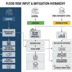
![Technical infographic showing the workflow of flood risk assessment for data centres, including hydrological inputs and mitigation strategies.]()
Flood Risk Assessment for Data Centres: Engineering Design Guide
![Isometric engineering rendering of a data centre campus featuring flood protection barriers and elevated utility infrastructure for disaster resilience.]()
Flood Protection Level Selection for Mission-Critical Data Centre Infrastructure
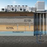
![Cross-section diagram of a data centre foundation showing soil strata, pile foundations, and groundwater monitoring wells for geotechnical analysis.]()
Geotechnical Requirements for Data Centres: A Structural Engineering Guide
![Civil 3D interface showing a 3D site grading model with color-coded cut and fill zones for earthwork optimization.]()
Optimizing Cut and Fill Operations Using Civil 3D and GIS
![3D digital terrain model showing site grading, flood protection levels, and cut-fill zones for industrial infrastructure development.]()
Establishing FPL and Estimating Cut Fill Quantities for Site Grading
![3D engineering model showing cut and fill optimization for industrial site grading and earthwork balancing.]()
Cut and Fill Optimization: 8 Engineering Studies for Site Grading