Table of Contents
Mastering Centrifugal Pump vs Positive Displacement Pump Selection
In my 20-plus years of troubleshooting piping systems in refineries, chemical plants, and offshore platforms, I have seen millions of dollars wasted because of a simple, fundamental mistake: selecting the wrong pump type for the process fluid. The battle between centrifugal and positive displacement (PD) pumps is not about which machine is superior. Instead, it is about understanding how their contrasting operating principles interact with your piping system’s hydraulics.
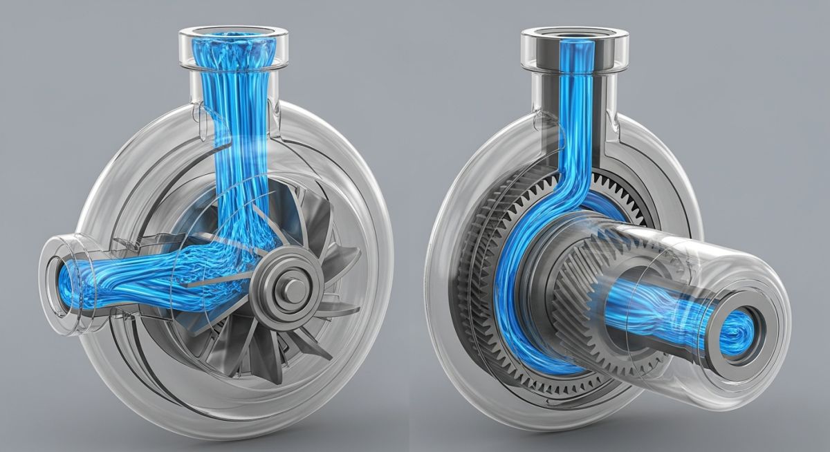
A centrifugal pump is a dynamic machine that adds kinetic energy to the fluid, converting velocity into pressure head. A positive displacement pump, on the other hand, is a constant-volume machine that physically traps a fixed quantity of fluid and forces it into the discharge pipe. This basic difference changes how they handle viscosity, pressure changes, and flow control.
Key Engineering Takeaways
- Centrifugal pumps are head-dependent machines where flow rate decreases as system resistance increases.
- Positive displacement pumps deliver a constant flow rate regardless of system pressure, making discharge relief valves mandatory.
- Fluid viscosity is the ultimate decider; high-viscosity fluids degrade centrifugal efficiency but actually improve positive displacement volumetric efficiency.
- Flow control methods differ fundamentally: centrifugal pumps use discharge throttling or speed control, while PD pumps require speed control or bypass loops.
- Pulsation dampeners are frequently required on reciprocating PD pumps to protect downstream piping from fatigue failure.
Complete Course on
Piping Engineering
Check Now
Key Features
- 125+ Hours Content
- 500+ Recorded Lectures
- 20+ Years Exp.
- Lifetime Access
Coverage
- Codes & Standards
- Layouts & Design
- Material Eng.
- Stress Analysis
Evaluating Centrifugal Pump vs Positive Displacement Pump Hydraulics
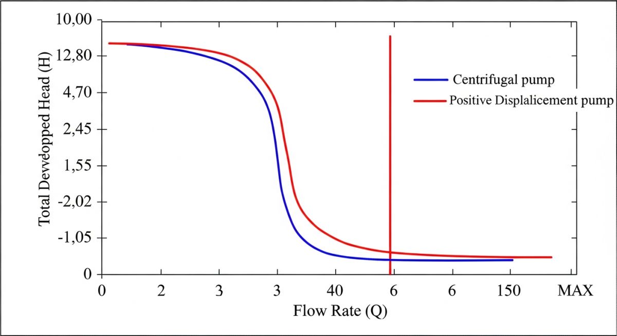
To truly understand these machines, we must look at their performance curves. For a centrifugal pump, the Head-Flow (H-Q) curve is sloping. As you throttle the discharge valve to increase system resistance (head), the flow rate decreases. If you run a centrifugal pump against a completely closed valve (shut-off head), the pump will consume minimum power (for low specific speed pumps) but will rapidly heat up the trapped fluid, leading to flashing and mechanical seal failure.
Conversely, a positive displacement pump has a nearly vertical H-Q curve. The flow rate remains virtually constant regardless of the discharge pressure. The only slight drop in flow at high pressures is due to “slip”—the internal leakage of fluid from the high-pressure discharge side back to the low-pressure suction side through internal clearances.
Never install a positive displacement pump without a fully rated safety relief valve (SRV) on the discharge line upstream of the first isolation valve. Because a PD pump will attempt to deliver its fixed volume regardless of downstream resistance, closing a discharge valve will cause the pressure to rise instantly until the motor stalls, the piping ruptures, or the pump casing explodes.
The Impact of Fluid Viscosity
Viscosity is where these two technologies diverge dramatically. Centrifugal pumps rely on high-speed fluid shear. When viscosity increases, the frictional losses inside the impeller passages skyrocket. This causes a severe drop in head, a massive reduction in flow rate, and a steep decline in mechanical efficiency. According to the Hydraulic Institute (HI) standards, once fluid viscosity exceeds 100 Centistokes (cSt), you must apply heavy derating factors to centrifugal performance.
Positive displacement pumps thrive on viscosity. Because they operate at lower internal velocities and rely on tight mechanical clearances, high-viscosity fluids reduce internal slip. This actually increases the volumetric efficiency of rotary gear, screw, and lobe pumps. While a centrifugal pump becomes useless when pumping heavy lube oils, polymers, or resins, a PD pump handles them with ease.
Mathematical Relationships and Calculations
For centrifugal pumps, the relationship between speed, flow, head, and power is governed by the Affinity Laws:
- Flow Rate (Q) is directly proportional to speed (N): Q2 / Q1 = N2 / N1
- Head (H) is proportional to the square of speed: H2 / H1 = (N2 / N1) squared
- Brake Horsepower (BHP) is proportional to the cube of speed: P2 / P1 = (N2 / N1) cubed
For positive displacement pumps, the theoretical flow rate is calculated based on displacement per revolution:
Q_theoretical = Displacement per Revolution * Pump Speed (RPM)
The actual flow rate is then determined by subtracting the internal slip:
Q_actual = Q_theoretical – Q_slip
Where slip is inversely proportional to fluid viscosity and directly proportional to the differential pressure across the pump.
The following table provides a direct engineering comparison between centrifugal and positive displacement pumps under standard industrial operating conditions. These parameters should guide your initial selection process.
| Performance Parameter | Centrifugal Pumps (API 610 / ASME B73.1) | Positive Displacement Pumps (API 674 / 676) |
|---|---|---|
| Flow Rate vs. Pressure | Flow varies significantly with system head changes. | Flow remains virtually constant as pressure changes. |
| Maximum Viscosity Limit | Typically limited to 100-150 cSt without severe derating. | Can handle up to 1,000,000 cSt (e.g., screw/gear pumps). |
| Efficiency at High Viscosity | Decreases rapidly due to high internal friction. | Increases or remains stable as internal slip decreases. |
| Self-Priming Capability | No (requires priming or foot valve, unless self-priming design). | Yes (inherently self-priming due to positive sealing action). |
| Flow Control Method | Discharge throttling valve or Variable Frequency Drive (VFD). | VFD or bypass line back to the suction source. |
| Discharge Pulsations | Smooth, continuous, pulse-free flow. | Pulsating flow (especially reciprocating designs). |
| Shear-Sensitive Fluids | High shear rates can damage sensitive fluids/emulsions. | Low shear rates (ideal for polymers, latex, and food products). |
This matrix maps specific pump sub-types to their governing industry standards, typical applications, and key design limitations.
| Pump Sub-Type | Governing Standard | Primary Application | Key Design Limitation |
|---|---|---|---|
| Overhung Single-Stage Centrifugal | API 610 (OH2) / ASME B73.1 | Hydrocarbon processing, water transfer, chemical feed. | Limited head capability per stage; sensitive to dry running. |
| Reciprocating Plunger / Piston | API 674 | High-pressure washdown, chemical injection, crude pipeline. | High vibration; requires pulsation dampeners on piping. |
| Rotary Twin-Screw | API 676 | Heavy oil transfer, multiphase fluid pumping, tank stripping. | High manufacturing cost; tight clearances sensitive to solids. |
| Controlled Volume Diaphragm | API 675 | Precise chemical dosing, water treatment additives. | Limited flow capacity; diaphragm rupture risk. |
Applying Centrifugal Pump vs Positive Displacement Pump Checklists
Before you press the start button on any newly installed pump, you must perform a series of rigorous field checks. In my experience, skipping these steps is the leading cause of infant mortality in rotating equipment. The checklist below highlights the critical verification points for both pump categories.
Field Verification Checkpoints
-
Piping Strain Verification (Both Types): Dial indicators must be placed on the pump shaft couplings while the suction and discharge flanges are bolted up. Shaft movement must not exceed 0.05 mm (0.002 inches) in any direction to prevent casing distortion.
-
Safety Relief Valve (SRV) Verification (PD Pumps Only): Confirm that an SRV is installed upstream of the discharge isolation valve. Verify that the SRV setpoint is calibrated to no more than 10% above the maximum operating pressure or the pump casing design pressure, whichever is lower.
-
Rotational Direction Check (Both Types): Uncouple the motor and perform a brief “solo run” to verify correct motor rotation. Running a centrifugal pump backward can unscrew the impeller, while running a PD pump backward reverses the suction and discharge ports, potentially overpressuring the suction piping.
-
Pulsation Dampener Pre-Charge (Reciprocating PD Pumps): Check the nitrogen pre-charge pressure in the pulsation dampeners. It should typically be set to 60% to 80% of the mean operating discharge pressure to ensure effective pressure wave attenuation.
-
Minimum Flow Bypass Line (Centrifugal Pumps): Ensure the minimum flow bypass line is open and the restriction orifice is correctly sized. This prevents the pump from operating below its Minimum Continuous Stable Flow (MCSF) limit during startup.
Field Case Study: Real-World Application
At a coastal crude oil terminal, a double-suction centrifugal pump designed to transfer heavy crude oil (viscosity ranging from 150 cSt to 450 cSt depending on seasonal temperatures) suffered from chronic mechanical seal failures, high motor power consumption, and severe piping vibration. The pump was operating far to the left of its Best Efficiency Point (BEP) because the high viscosity of the cold crude oil had drastically increased the system head, reducing the flow rate to 40% of design. The high shear rates inside the pump casing caused localized heating, which flashed the volatile organic compounds in the crude, dry-running the mechanical seals.
I was brought in to analyze the system hydraulics. After reviewing the viscosity profile, I recommended replacing the centrifugal pump with an API 676 twin-screw positive displacement pump. Because the twin-screw pump handles high-viscosity fluids with minimal shear and high volumetric efficiency, the flow rate became independent of the seasonal temperature and viscosity fluctuations.
The results were immediate: piping vibration dropped by 85%, mechanical seal life extended from an average of 3 weeks to over 3 years, and the motor power consumption decreased by 30% during cold-weather operations.
Direct Engineering Recommendation: When dealing with fluids whose viscosity varies significantly due to temperature changes, do not attempt to oversize a centrifugal pump to overcome the friction losses. Instead, select a rotary positive displacement pump that will maintain a constant flow rate and operate efficiently across the entire viscosity spectrum.
Frequently Asked Engineering Questions
How does fluid viscosity affect centrifugal pump efficiency compared to positive displacement pumps?
Why is a safety relief valve mandatory on the discharge of a positive displacement pump?
Can centrifugal pumps run dry without causing immediate damage?
What is the difference in flow control methods between these two pump types?
How do NPSH requirements differ between centrifugal and positive displacement pumps?
Which pump type is better suited for shear-sensitive fluids?

📚 Recommended Resources: centrifugal pump vs positive displacement pump
Read these Guides


Related posts:
![Industrial worker reviewing a Material Safety Data Sheet on a tablet near chemical storage.]()
What is Material Safety Data Sheet (MSDS)? | MSDS VS SDS
![Aerial view of a modern municipal wastewater treatment plant featuring circular clarifiers and aeration basins.]()
Wastewater Treatment: Process Steps, Design Considerations, and Plant Types
![An offshore crude oil drilling rig operating in the ocean at sunset.]()
Understanding Crude Oil Price and Types for Piping Design
![Steel sucker rod string being installed at an oil well pumpjack site.]()
What is a Sucker Rod? Its Types and Critical Importance
![Cutaway diagram of a fire-safe ball valve showing primary and secondary metal-to-metal seals.]()
What is Fire-Safe Valve? API 607 vs API 6FA
![A maintenance engineer inspecting industrial machinery with a digital diagnostic overlay.]()
Optimizing Plant Reliability with the Core Types of Maintenance